Three-dimensional image coding by merger of left and right images

a three-dimensional image and image sequence technology, applied in the field of three-dimensional image sequence signal encoding and decoding, can solve the problems of difficult to achieve uniform picture quality, complicated timing control and picture code management, and separate processing of main and sub

Inactive Publication Date: 2000-06-13
VISION3D TECH
View PDF26 Cites 83 Cited by
  • Summary
  • Abstract
  • Description
  • Claims
  • Application Information

AI Technical Summary

Problems solved by technology

With respect to the first or second methods, however, separate processing of the main and sub-pictures, as described above, complicates timing control and picture code management.
With either first or second methods, uniform picture quality is difficult to achieve

Method used


Image

  • Three-dimensional image coding by merger of left and right images
  • Three-dimensional image coding by merger of left and right images
  • Three-dimensional image coding by merger of left and right images

Examples


first embodiment

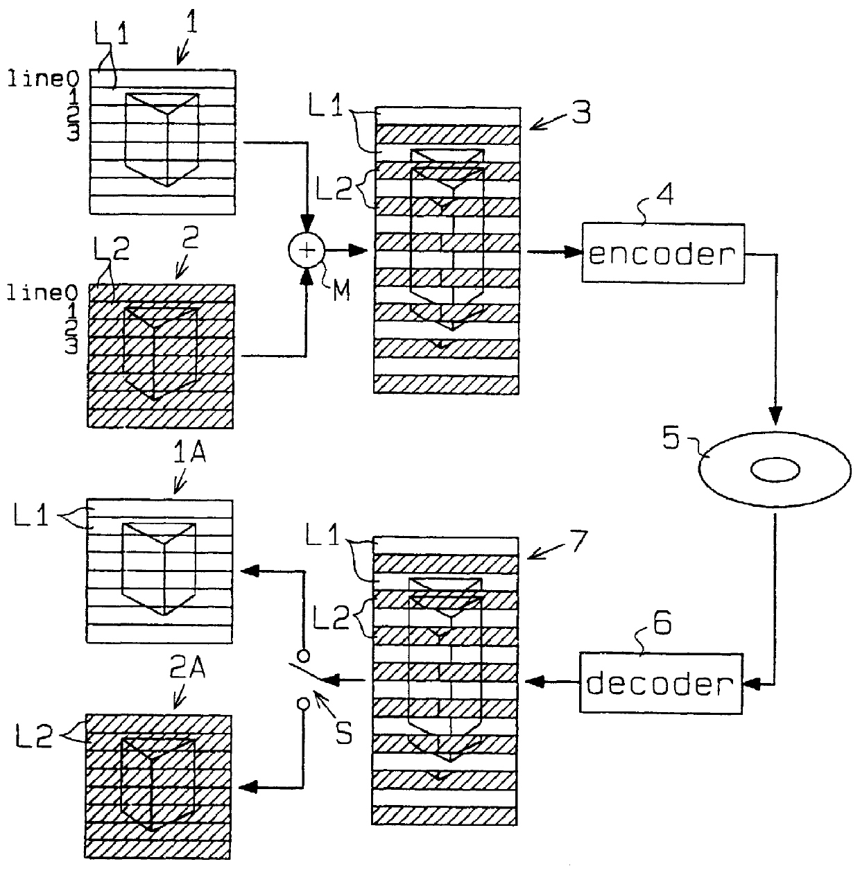
A detailed example will now be described with reference to FIGS. 4 through 14. FIG. 4 schematically illustrates an apparatus to encode a 3D image sequence signal. The apparatus comprises a mixer 20 and an MPEG-1 compliant encoder 22. As shown in FIG. 5, the mixer 20 receives simultaneous input of a right-eye image sequence RV and a left-eye image sequence LV. The mixer 20 then merges both sequences, line by line, to produce a merged picture signal DV having a twice the number of vertical lines present in signals RV or LV. The MPEG-1 encoder 22 then receives and encodes the merged picture signal DV from the mixer 20. An optical pickup 24 receives the encoded data, output from the MPEG-1 encoder 22, and records the data on a magneto-optical disk 26.

FIG. 6 presents a block circuit diagram of the mixer 20. In FIG. 6, the mixer 20 includes a first image memory 32 for storing a right-eye picture signal RV sensed by a first camera 28, a second image memory 34 for storing a left-eye pictur...

second example of first embodiment

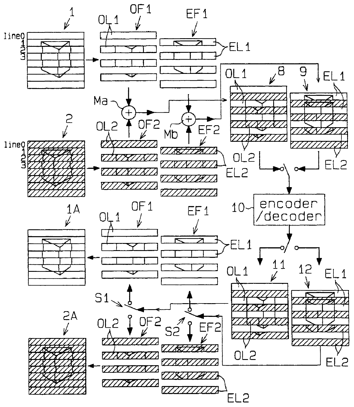
A more detailed second example according to the first embodiment will now be described with reference to FIG. 15. As shown in FIG. 15, a mixer 40 has a horizontal pulse generator 42 and a switch 44. In response to a sync signal SYNC from the first camera 28, the horizontal pulse generator 42 produces a pulse signal to invert the horizontal scanning period. The pulse signal is output to the switch 44. The switch 44 receives the left and right image sequence signals from the first and second cameras 28 and 30, and switches during each horizontal scanning period in response to the pulse signal. The switching alternates the output of the right and left image sequence signals, line by line. Unlike the first example which reads the right and left image sequence signals at a double speed and merges those signals, the second example alternately outputs the right picture and left picture line by line. This produces a merged picture sized the same as the frame forming the right and left pictu...

third example of first embodiment

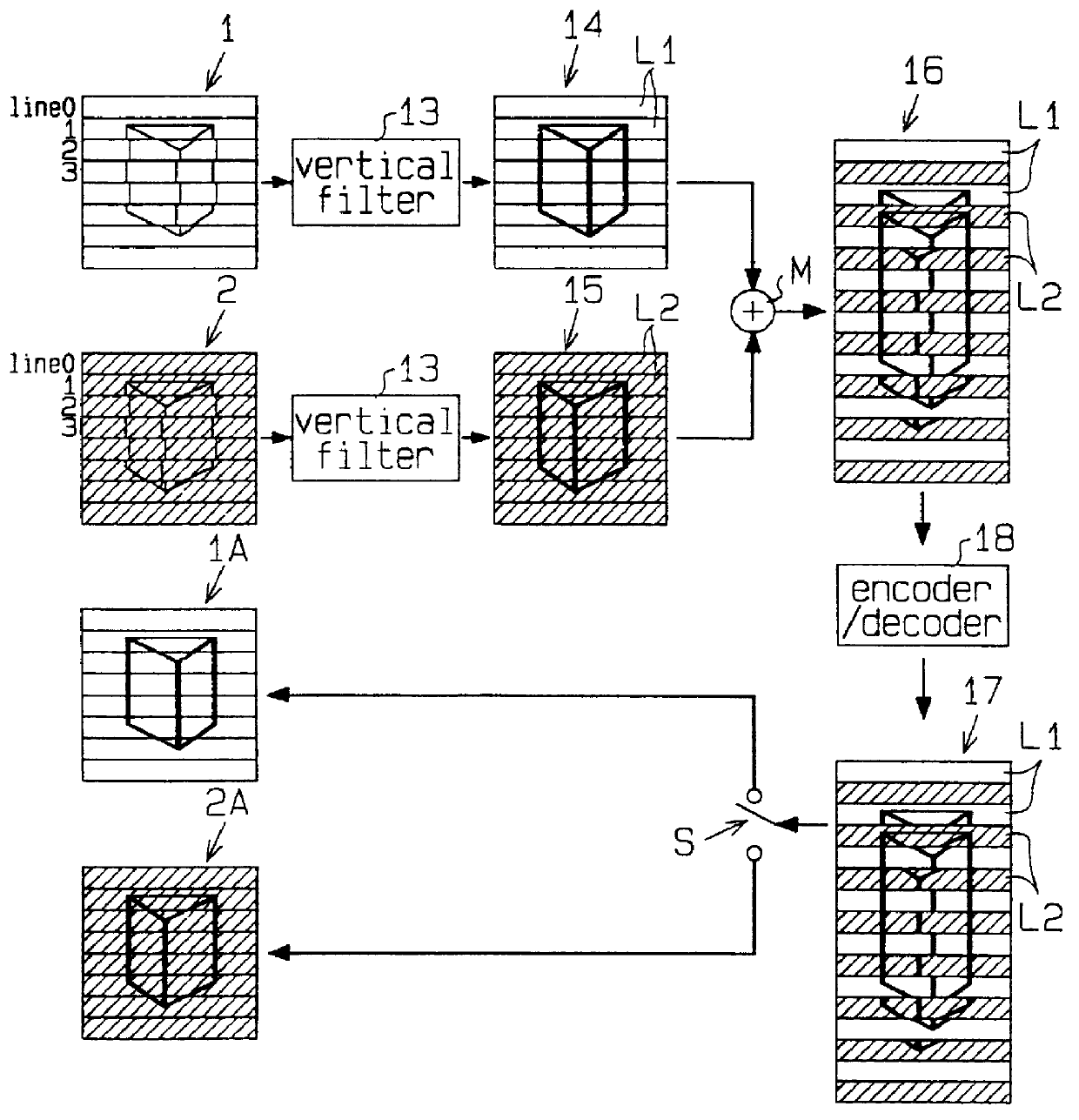
A third example according to the first embodiment will now be described with reference to FIGS. 16 to 25. As shown in FIG. 16, a 3D image sequence encoding apparatus comprises the mixer 20 and an MPEG-2 compliant encoder 46 set up in a frame structure mode. The mixer 20, like the mixer in the first example, merges right and left image sequences RV, LV in alternating fashion, line by line, to produce a merged picture DV. The number of vertically scanned horizontal lines in picture DV is doubled from that of either picture LV or RV. The MPEG-2 encoder 46 encodes the merged picture DV, and the optical pickup 24 records the encoded data on the magneto-optical disk 26.

FIG. 17 presents a block circuit diagram of the MPEG-2 encoder 46. For clarity, the reference numerals used for components of the encoder 22 described in the first example will again be used for this example. The encoder 46 further includes a frame / field block converter 145 and an inverse frame / field block converter 146. Th...


PUM


Abstract

A method is disclosed, for encoding a signal with a three dimensional image sequence using a series of left and right images. Each image in the left image series is a picture formed by non-interlaced or interlaced scanned left line images, and each image in the right image series is a picture formed by non-interlaced or interlaced scanned right line images. The left line images contained in the left picture are merged with the right line images contained in the right picture to produce an alternately arranged left and right line merged picture. The merged picture is encoded using an MPEG-2 compliant encoder.

Description

1. Field of the InventionThe present invention relates generally to a method and apparatus for encoding and decoding a three dimensional (3D) image sequence signal, and in particular, to a method and apparatus of encoding and decoding a 3D image sequence signal containing image sequences for left and right eye viewing.2. Description of the Related ArtThere are three common ways to encode a digital 3D image sequence signal containing left and right eye images. The first method directly encodes a main picture, intended for the right eye, and an indirectly encodes a sub-picture, intended for the left eye. The sub-picture image is formed by parallactic compensation or reference to the main picture. The main and sub pictures are then compressed according to the method described in Japanese Unexamined Patent Publication No. 6-153239. The second method directly encodes a main picture and indirectly encodes a first sub picture, using parallax and motion compensation, with reference to the m...

Claims


Application Information

Patent Timeline
IPC IPC(8): G06T9/00H04N13/00H04N13/239
CPCG06T9/007H04N13/0048H04N13/0051H04N13/0055H04N19/597H04N13/0003H04N13/0037H04N13/0239H04N13/0296H04N2013/0077H04N2013/0085H04N2013/0096H04N13/0059H04N13/167H04N13/194H04N13/189H04N13/161H04N13/296H04N13/10H04N13/15H04N13/239
Inventor URANO, TAKASHIKODAMA, HIDEOHAMAMOTO, YASUHACHISUGIMOTO, ETSUKOKOBAYASHI, SATOKO
Owner VISION3D TECH
Why Eureka
Try Eureka