Conveyor belt scrapers

a technology of conveyor belts and scrapers, which is applied in the direction of conveyor parts, cleaning, transportation and packaging, etc., can solve the problems of inconvenient adjustment of crossbars in conventional practice, shafts can easily jam in guides, and the end of blades are excessively loaded

Inactive Publication Date: 2000-06-20
MAT GHISLAIN JUSTIN MARIE
View PDF11 Cites 55 Cited by
  • Summary
  • Abstract
  • Description
  • Claims
  • Application Information

AI Technical Summary

Problems solved by technology

However, the above-mentioned phenomenon of differential rates of wear between the central and end regions of the blade makes it impossible in conventional practice to adjust the crossbar in such a way that all regions of the worn blade are loaded equally against the belt.
Since most of the scraping action takes place in the central region of the belt, it often happens that the ends of the blade are excessively loaded in order to obtain an acceptable upward load on the more worn central region of the blade or, in the case of a segmented blade, on the more worn, c...

Method used


Image

  • Conveyor belt scrapers
  • Conveyor belt scrapers
  • Conveyor belt scrapers

Examples


second embodiment

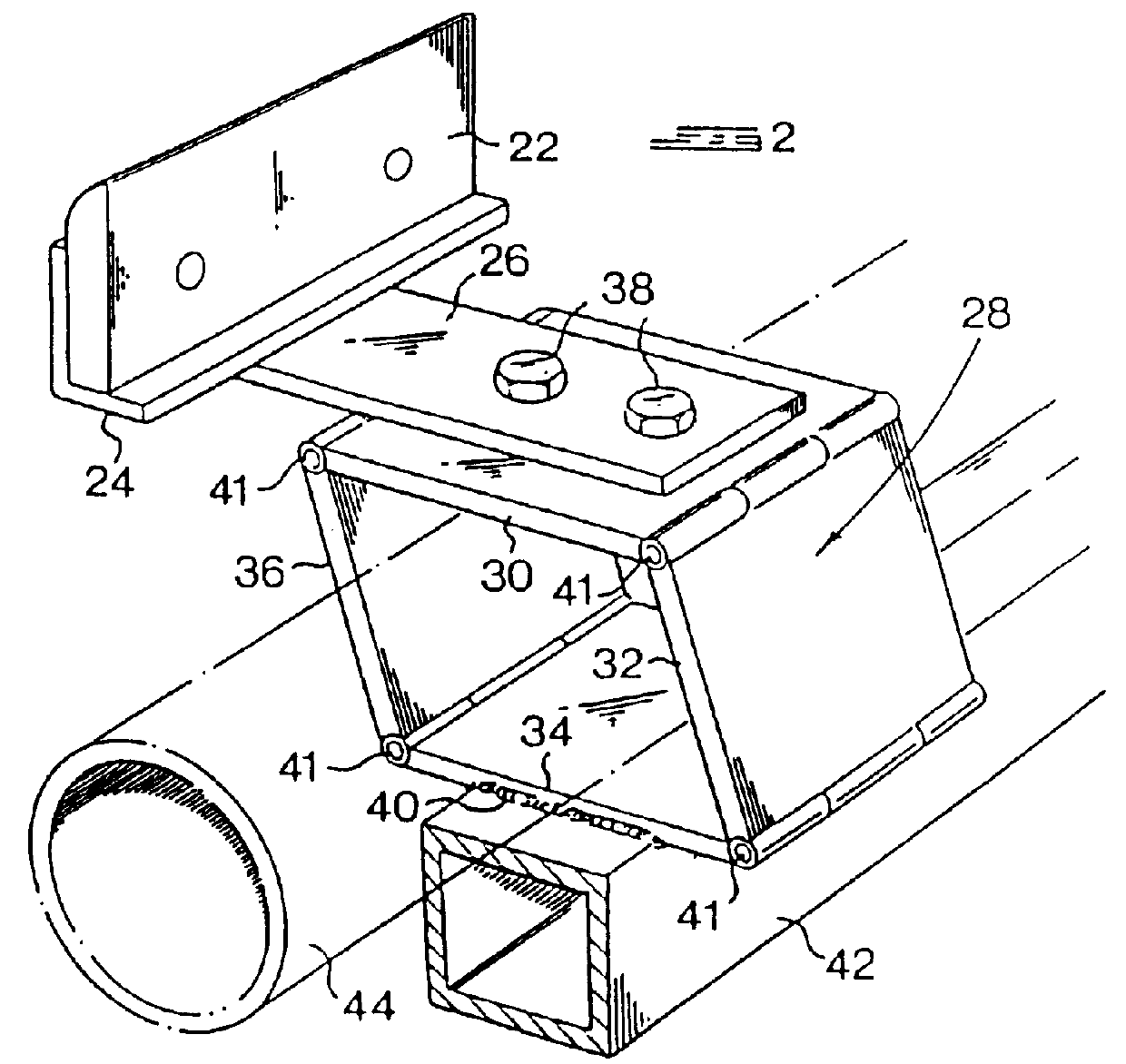
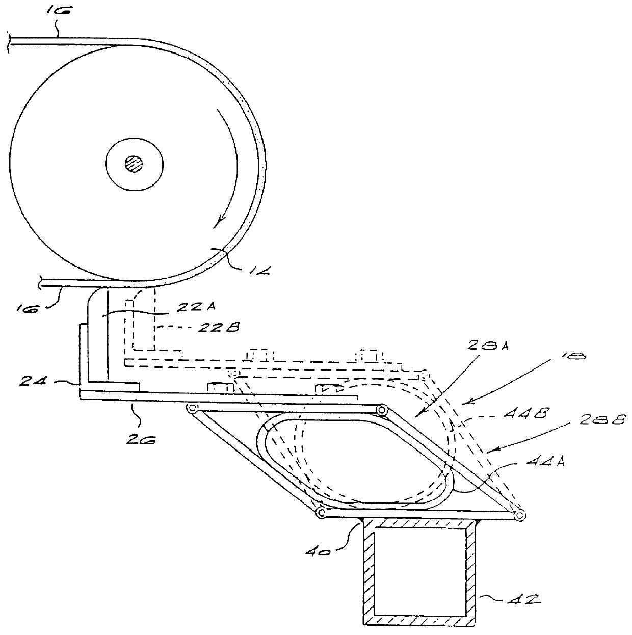
FIGS. 4 and 5 illustrate the invention in which air inflation is also used to deform the parallelogram linkages of the blade segment supports but in which such inflation is achieved without the use of a single tube 44 extending through all the linkages. In these Figures, components corresponding to those seen in FIGS. 1 to 3 are designated with the same reference numerals.

first embodiment

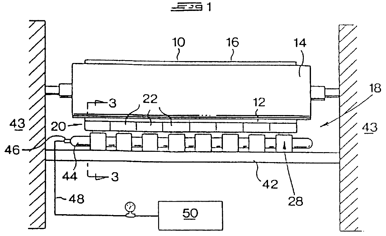
In FIGS. 4 and 5, a round disc 54 is welded to the underside of the link 30 of each parallelogram linkage. Welded to the top surface of the link 34 is a round disc 56 of the same diameter. The ends of a flexible hose 58 are located about the discs and are secured there in airtight manner by circumscribing clamps 60 which may, for instance, be in the form of Jubilee clips. A port 62 is formed through the lower disc 56 and through the link 34 and communicates with the interior of the airtight hose 58. An inflation nipple 64 is connected to the port and to a manifold 66. The manifold 66, which is connected to the source 50, thus serves all the hoses 58. As in the first embodiment, the source 50 may be an air compressor or a pressure vessel charged with air under pressure.

The freely hinged nature of the links 30, 32, 34 and 36, together with the flexibility of the hoses 58, enables the blade segment supports to assume a collapsed configuration before the hoses 58 are pressurised. The st...


PUM


Abstract

PCT No. PCT/EP96/04228 Sec. 371 Date Feb. 20, 1998 Sec. 102(e) Date Feb. 20, 1998 PCT Filed Sep. 27, 1996 PCT Pub. No. WO97/14635 PCT Pub. Date Apr. 24, 1997The invention concerns a conveyor belt scraper used to scrape debris from the surface of a conveyor belt (10). The scraper incorporates a segmented scraper blade which includes individual blade segments (22) arranged side by side with one another such that in use each blade segment scrapes a portion of the width of the belt surface. For blade segment there is a blade segment support (28) on which the associated blade segment (22) is supported. Each blade segment support (28) includes pivotally interconnected links (30, 32, 34, 36) forming a closed parallelogram linkage. A support structure (42, 82) is provided to support the parallelogram linkages in side by side relationship adjacent the belt surface. Gas-inflatable biasing means (44, 58) act on the parallelogram linkages such that inflation thereof causes the linkages to deform in a manner to displace the blade segments (22) in a direction lengthwise of the belt (10) and towards the belt surface. During such displacement, each blade segment (22) moves parallel to itself and maintains a constant inclination to the vertical.

Description

BACKGROUND TO THE INVENTIONTHIS invention relates to conveyor belt scrapers.To avoid spillage, conveyor belts are not generally loaded to full capacity. Thus the material which is being conveyed on the belt is located on the central region of the upper run of the belt and very little, if any, material is in contact with the lateral extremities of the belt. On the return run of the belt, one or more scrapers are arranged to scrape any adhering material from the belt surface. For instance, a scraper may be positioned generally below the head or discharge roller where the belt is initially reversed on the return run.Known belt scrapers either have a one-piece or segmented scraper blade, the latter being composed of a series of side-by-side blade segments, arranged to scrape the full width of the belt on the return run. Because little if any material was initially in contact with the lateral extremities of the belt on the upper run, the ends of the scraper blade are required to perform ...

Claims


Application Information

Patent Timeline
IPC IPC(8): B65G45/00B65G45/16
CPCB65G45/16
Inventor MAT
Owner MAT GHISLAIN JUSTIN MARIE
Why Eureka
Try Eureka