Wheel hub or hub unit allowing improved mounting and removal of a brake member

a technology of hub or hub unit and brake member, which is applied in the direction of axially engaging brakes, mechanical equipment, braking systems, etc., can solve the problems of brake disc distortion and adverse effects on the braking surfa

Inactive Publication Date: 2000-06-20
SKF IND SPA
View PDF35 Cites 55 Cited by
  • Summary
  • Abstract
  • Description
  • Claims
  • Application Information

AI Technical Summary

Problems solved by technology

These prior art solutions have an inconvenience in that the tightening of the wheel bolts causes distortion of the brake disc.
Also, under the influence of temperature variation, the braking surface is adversely affected by distortion due to the aforecited securing arrangement.

Method used


Image

  • Wheel hub or hub unit allowing improved mounting and removal of a brake member
  • Wheel hub or hub unit allowing improved mounting and removal of a brake member
  • Wheel hub or hub unit allowing improved mounting and removal of a brake member

Examples


Embodiment Construction

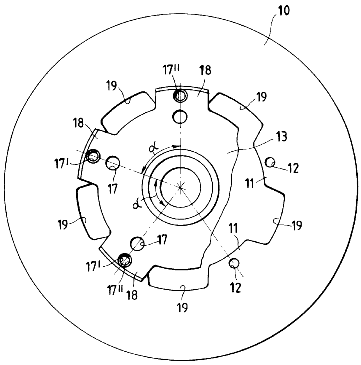
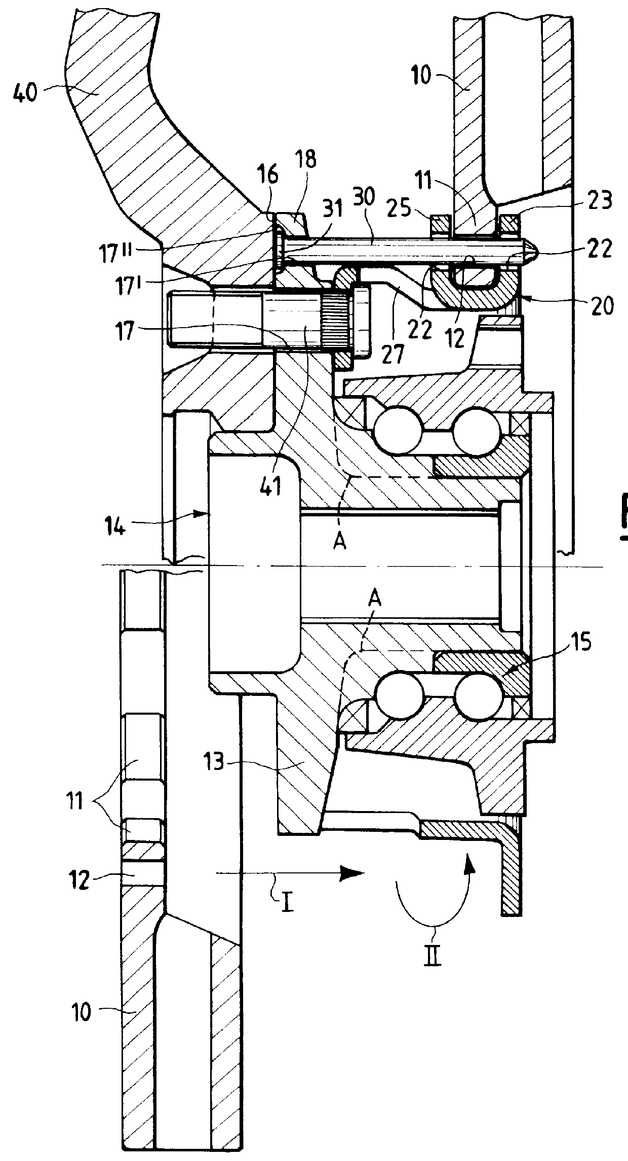
Referring initially to FIG. 1, numeral 10 designates overall a brake member, in this instance a brake disc, of known kind consisting of an annular disc. The inner edge of the disc forms a plurality of radial ears 11 angularly equally spaced with an angular pitch .alpha.. The radial ears 11 protrude towards the central axis of rotation of the hub unit. A through hole 12 is provided in each ear 11 for fixing to a radial rotating flange 13 of the wheel hub 14, as shown in FIG. 2. In the various embodiments described and shown in the following, the hub 14 also forms on of the two inner races of the hub bearing (designated overall at 15), but it is understood that the present invention is equally applicable to solutions wherein both of the inner races are formed by separate rings, as indicated schematically by phantom line A in FIG. 2.

Still referring to FIG. 2, as disclosed in Italian Patent application No. IT-TO96A000387 to the same Applicant, an intermediate connecting member 20 of ann...


PUM


Abstract

There is disclosed a wheel hub or hub unit of the type having a radial hub flange (13) providing connection to the wheel (40) and to a brake member (10) having an annular disc portion having a plurality of ears (11) radially protruding from its inner edge. The hub flange (13) defines a plurality of axial passages, in the form of peripheral radial recesses (19) or bores (17, 17') for slipping a plurality of axial pins (30) to be fitted in holes (12) obtained in the brake member ears (11) and in openings (22) obtained in at least one radial wall (23) of a brake carrier (20) rotatably fast with the hub (14) to rotationally secure the brake member (10) to the hub. When the wheel (40) is mounted on the outside of the hub flange, axial movement of the pins towards the outside is stopped by the wheel.

Description

DESCRIPTION1. Field of the InventionThe present invention generally relates to wheel hubs or hub units having a disc or drum brake member comprising an annular disc the inner edge of which forms a plurality of radial ears. More particularly, the invention refers to a wheel hub or hub unit allowing to mount and remove a brake member of the said kind from the outside of the vehicle onto a brake carrier which is located on the inner side of the hub flange. The invention pertains to the mounting and securing of the brake disc on the brake carrier.2. Background of the InventionKnown motor vehicle wheel hubs form a radial flange for connecting to the wheel and the brake member, disc or drum. In conventional designs, as can be seen in FIG. 1A, the brake disc or drum is mounted on a hub or hub bearing unit by centring on a spigot diameter on the outside of the hub flange and being secured by a threaded coupling means and finally fixed by the wheel bolts or nuts.These prior art solutions hav...

Claims


Application Information

Patent Timeline
Patent Type & Authority Patents(United States)
IPC IPC(8): B60B27/00F16D65/12
CPCB60B27/00F16D65/123F16D65/128F16D2065/1392F16D2065/1316F16D2065/136
Inventor BERTETTI, PAOLORUTTER, ANDREAS
Owner SKF IND SPA
Why Eureka
Try Eureka