Coating porous carriers

a porous material and carrier technology, applied in the field of coating porous carriers, can solve the problems of inflexible metered penetration depth of a substance to be applied to a porous material web, difficulty in using the existing adjusting device to vary with sufficient sensitivity, and uncoated sections on the material web

Inactive Publication Date: 2000-06-20
BEMATEC
View PDF16 Cites 10 Cited by
  • Summary
  • Abstract
  • Description
  • Claims
  • Application Information

AI Technical Summary

Problems solved by technology

Due to the geometrical conditions of this apparatus, however, it is difficult to use the existing adjusting device to vary with sufficient sensitivity a pressure that acts upon the coating material substance between the doctor bar and material web or counterpressure roll during continuous operation.
The penetration depth o

Method used


Image

  • Coating porous carriers
  • Coating porous carriers
  • Coating porous carriers

Examples


second embodiment

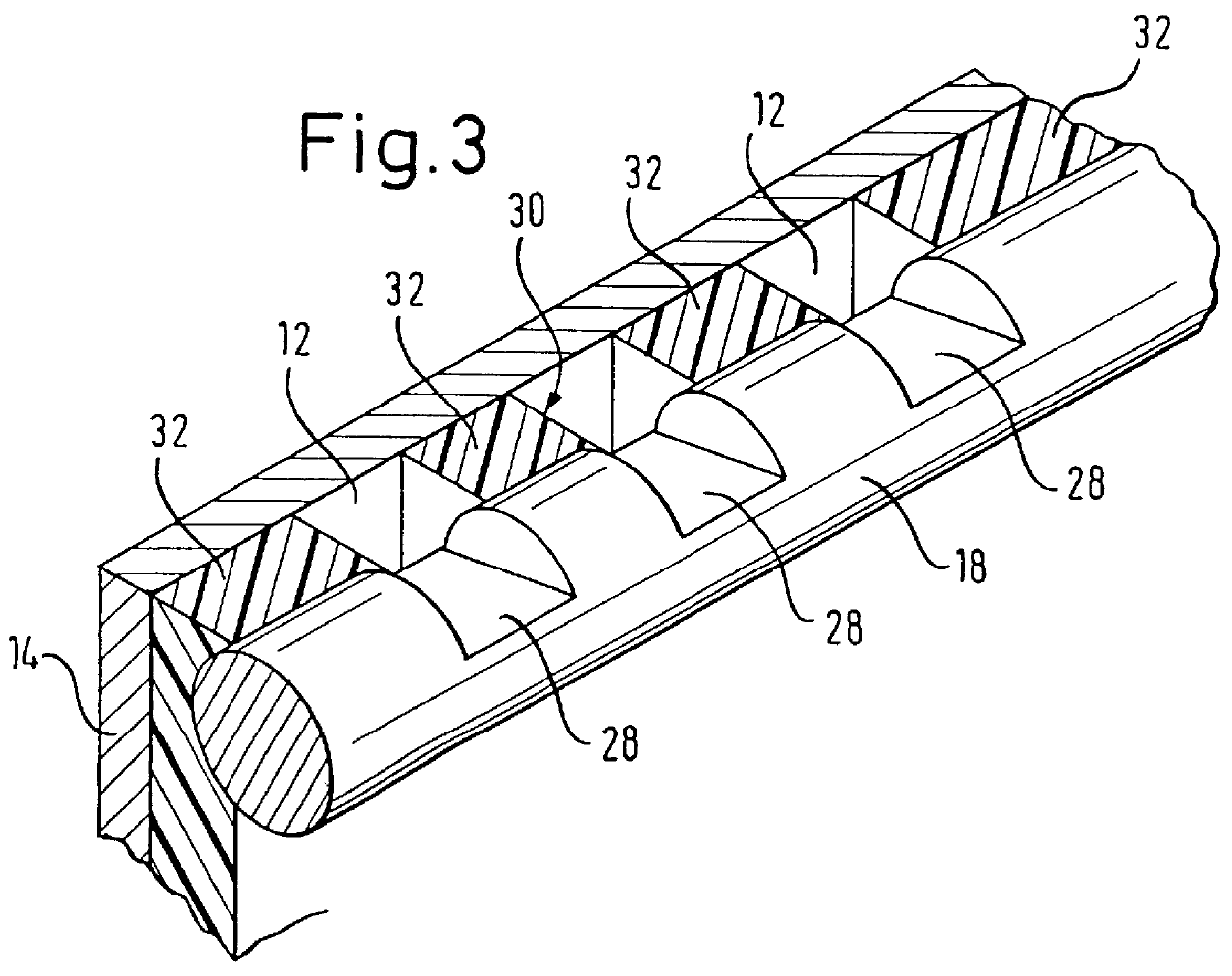
FIG. 2 shows a perspective view of a doctor bar of the coating apparatus according to the invention, and

third embodiment

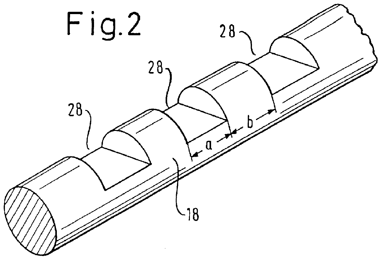
FIG. 3 shows a perspective view of a partial region of a coating apparatus according to the invention.

DESCRIPTION OF THE INVENTION'S EXEMPLARY EMBODIMENTS

To avoid repetitions, identical parts or components will also be identified by the same reference numerals in the following description and in the drawings, unless it is necessary to draw further distinctions.

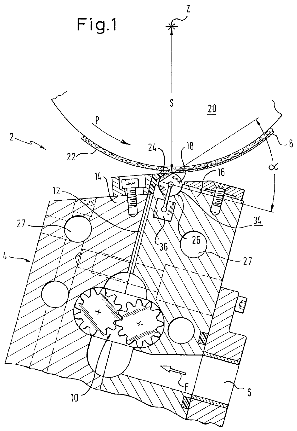
As shown in FIG. 1 in a schematic cross-sectional depiction, the coating apparatus 2 according to the invention comprises a slotted nozzle means 4 that extends across the entire width of the coating apparatus 2. A supply duct 6 for the coating material 8 to be applied is formed in the coating apparatus 2. A slotted-nozzle gap 12, connected via a gear pump 10 and formed between a stationary incoming nozzle lip 14 and a trailing nozzle lip 16, adjoins this supply duct 6. The feed direction of the coating material 8 is indicated in the drawing by arrow F.

A doctor bar 18 is disposed at the upper free end of the trailing nozzle lip...


PUM


Abstract

The invention relates to an apparatus for applying, by means of a slotted nozzle device formed between a stationary incoming nozzle lip and a trailing nozzle lip, a thin layer of coating material to a porous material web that passes over a counterpressure roll, wherein a doctor bar with an essentially circular cross-sectional shape is disposed on the trailing nozzle lip; this doctor bar has on its periphery at least one flattened section that runs across the entire longitudinal extension of the doctor bar and is rotatably supported within a doctor support so that the flattened section is adjustable at a setting angle relative to the counterpressure roll.

Description

The invention relates to an apparatus for applying a thin layer of coating material onto a porous material web.PRIOR ARTThe types of coating apparatus already known are ones in which a slotted nozzle device is used to provide a material web, which passes over a counterpressure roll and is for example made of paper, plastic, woven fabric material, metal foil or a combination of these materials, on one side with a layer of coating material, such as hot melts, high-viscosity adhesives, paraffins and microcrystalline waxes or the like. The coating material, having emerged from a nozzle slot formed between a stationary incoming nozzle lip and a trailing nozzle lip of the slotted nozzle device, is applied directly to the surface of the continuous material web via a doctor bar formed in the trailing nozzle lip, with the material web being supported on a revolving support face during application.An apparatus of the above class with a slotted nozzle device for applying a thin layer of coatin...

Claims


Application Information

Patent Timeline
IPC IPC(8): B05C11/02D06B1/08D06B1/00D21H23/00D21H23/34B05C3/00B05C3/18B05C5/02B05C11/04
CPCD21H23/34D06B1/08B05C11/025B05C3/18
Inventor HERZOG, PETER
Owner BEMATEC
Why Eureka
Try Eureka