Electronic ballast with inrush current limiting

a technology of inrush current and electronic ballast, which is applied in the direction of emergency protective arrangements for limiting excess voltage/current, electric discharge lamps, electrical equipment, etc., can solve the problem that the advantage of such a simple circuit for limiting inrush current cannot be utilized, and the effect of limiting inrush curren

Inactive Publication Date: 2000-06-20
PATENT TREUHAND GESELLSCHAFT FUR ELECTRIC GLUEHLAMPEN MBH
View PDF2 Cites 19 Cited by
  • Summary
  • Abstract
  • Description
  • Claims
  • Application Information

AI Technical Summary

Problems solved by technology

The advantage of such a simple circuit for limiting the inrush current cannot, however, be utilized straightforwardly in interaction with an inverter designed in a contemporarily customary manner, said inverter being constructed from a half-bridge arrangement.

Method used


Image

  • Electronic ballast with inrush current limiting
  • Electronic ballast with inrush current limiting
  • Electronic ballast with inrush current limiting

Examples


Embodiment Construction

Preferred exemplary embodiments of the invention are described in detail below with reference to the drawing, in which:

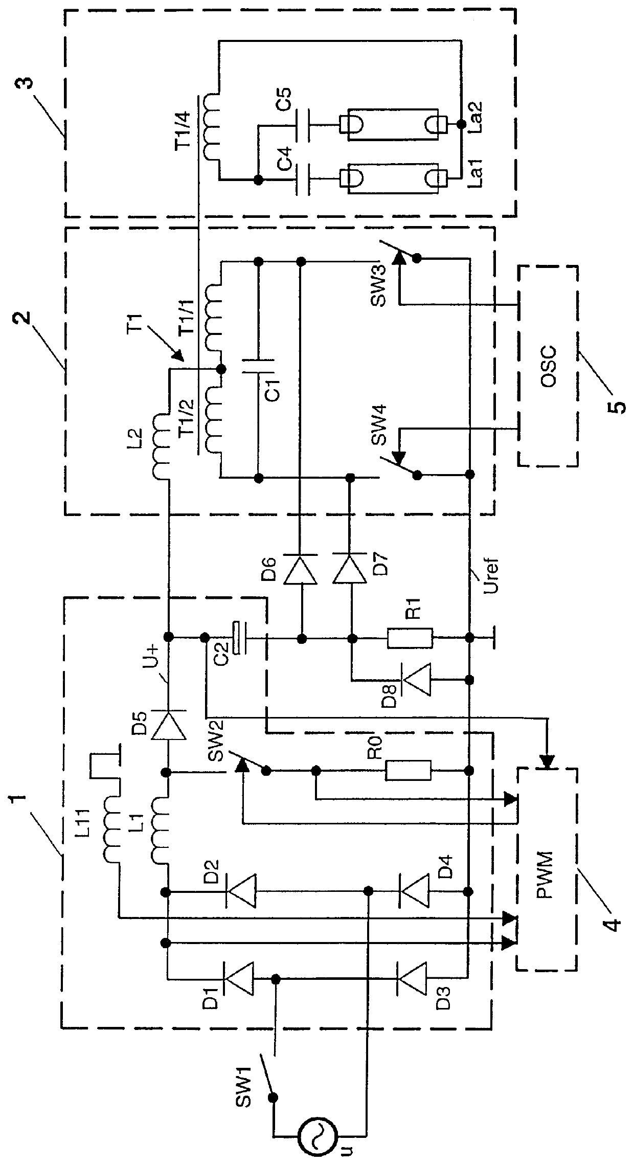
FIG. 1 shows a block circuit diagram of an electronic ballast having a rectifier arrangement which is connected to power supply voltage and feeds a stabilized DC voltage to a connected inverter which, for its part, supplies a lamp load circuit with a high-frequency pulse train, the rectifier arrangement being assigned a circuit for inrush current limiting in the form of a resistor arranged in its output stage,

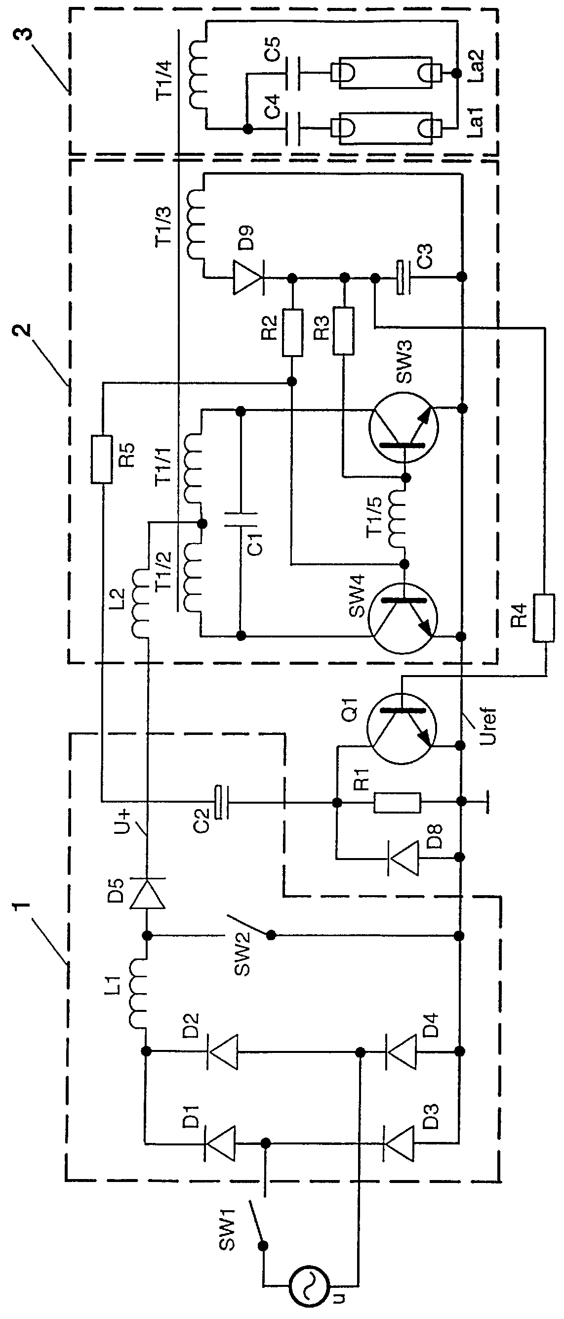
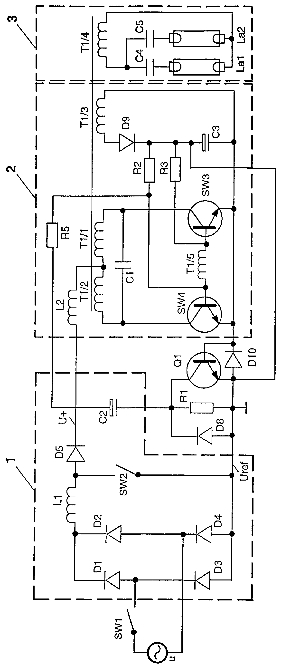
FIGS. 2, 3 in each case show a further embodiment of the electronic ballast according to FIG. 1, the circuit for inrush current limiting in each case having a switching transistor whose switching path is connected in parallel with the non-reactive resistor.

FIG. 1 illustrates a block circuit diagram of an electronic ballast for fluorescent lamps, in which a rectifier arrangement 1 is connected, on the input side, to AC power supply voltage u via a conventional p...


PUM


Abstract

The electronic ballast has a rectifier arrangement (1)-which is fed by AC power supply voltage (U)-with active step-up converter (SW2), a storage capacitor (C2), a network for limiting an inrush current and two outputs, at which a stabilized DC voltage (U+) referred to housing ground as reference potential (Uref) is output. An inverter (2) is connected to the rectifier arrangement, a load circuit (3) with at least one fluorescent lamp (La1 and / or La2) being assigned to said inverter on the output side. The inverter has a converter network (T1 / 1, T1 / 2, C1, SW3, SW4), preferably designed as a push-pull circuit, with two bridge paths, which, in the steady-state operating condition, are alternatively switched through to the reference potential. In this case, the switching network for limiting the inrush current comprises a limiting resistor (R1), which, in series with the storage capacitor (C2), is connected to reference potential. The junction point between the storage capacitor and the limiting resistor is coupled to the two bridge paths of the converter network in such a way that it is connected, in the steady-state condition of the inverter, via the latter to housing ground and the limiting resistor, which is thus effective only in the switch-on phase, is bridged.

Description

The invention relates to an electronic ballast for at least one fluorescent lamp in accordance with the preamble of patent claim 1.I. PRIOR ARTAs an operating circuit for fluorescent lamps which is usually fed from the public power supply system, an electronic ballast generally has a harmonic filter which is connected to the power supply voltage and to which a rectifier circuit with step-up converter is connected. By means of the latter, the rectified voltage in this particular group of power supply units is usually raised approximately to the peak value of the feeding AC voltage and held there. The step-up converter charges a storage capacitor in a defined manner up to the charge level predetermined thereby. This storage capacitor thus forms a voltage-stabilized output stage of the rectifier circuit. Supplying the load circuit containing the fluorescent lamp(s) with a high-frequency AC voltage, which, if appropriate, is also variable in terms of its frequency, is another special fe...

Claims


Application Information

Patent Timeline
Patent Type & Authority Patents(United States)
IPC IPC(8): H05B41/28H05B41/285H02H9/00
CPCH05B41/2856Y10S315/07
Inventor TWARDZIK, RENE
Owner PATENT TREUHAND GESELLSCHAFT FUR ELECTRIC GLUEHLAMPEN MBH
Why Eureka
Try Eureka