Stereoscopic viewing device and stereoscopic viewing method

a stereoscopic and viewing device technology, applied in the field of stereoscopic viewing devices and stereoscopic viewing methods, can solve problems such as image quality degradation

Inactive Publication Date: 2000-06-20
SONY CORP
View PDF4 Cites 38 Cited by
  • Summary
  • Abstract
  • Description
  • Claims
  • Application Information

AI Technical Summary

Benefits of technology

Therefore, according to the present invention, a stereoscopic image can be projected on a displaying means such that a flicker is eliminated and a deterioration of the image quality is prevented, owing to installation of a classifying means for classifying the input video signal respectively, on the basis of the level distribution pattern of plural pixels in the stated spatio-temporal region; a predictive blocking means for generating the pixel data for predictive calculation, by blocking the input video signal for every plural pixels in the stated spatio-temporal region; a predictive processing means which is previously having the plural sets of predictive coefficients which are respectively corresponding to the plural classes, and which processes the predictive calculation of the predictive calculating pixel data obtained on the basis of the output of the predictive blocking means, using the predictive coefficient which is corresponding to the classification result obtained on the basis of the output of the classifying means, out of the predictive coefficients of each said set, and hereby generates the video signal for left eye and the image signal for right eye respectively; and a display means for displaying the stereoscopic image on the basis of the video signal for left eye and the video signal for right eye which are obtained on the basis of the output of the predictive processing means.
Besides, according to the present invention, it is able to eliminate a flicker and to prevent a deterioration of the image quality, owing to the fact that the input video signal is classified respectively, on the basis of the level distribution pattern of each said pixel, for every plural pixels in the stated spatio-temporal region; and the pixel data for predictive calculation is generated, by blocking the input video signal for every plural pixels in the stated spatio-temporal region; and then the predictive calculation of the predictive calculating pixel data obtained on the basis of the output of the predictive blocking means is processed, utilizing the predictive coefficient which is corresponding to the classification result obtained on the basis of the output of the classifying means, out of the plural sets of predictive coefficients which are respectively corresponding to the plural classes which have been previously prepared, thereby generating the video signal for left eye and the image signal for right eye respectively; and then the stereoscopic image is displayed on the basis of the video signal for left eye and the video signal for right eye.

Problems solved by technology

Therefore, there has been such disadvantage that two times of quantity of information is required so as not to deteriorate the time resolution of the image, and if the quantity of the information is not increased, flicker occurs and the image quality is deteriorated because of deterioration of the time resolution.

Method used


Image

  • Stereoscopic viewing device and stereoscopic viewing method
  • Stereoscopic viewing device and stereoscopic viewing method
  • Stereoscopic viewing device and stereoscopic viewing method

Examples


Embodiment Construction

Preferred embodiments of this invention will be described with reference to the accompanying drawings:

(1) An Embodiment

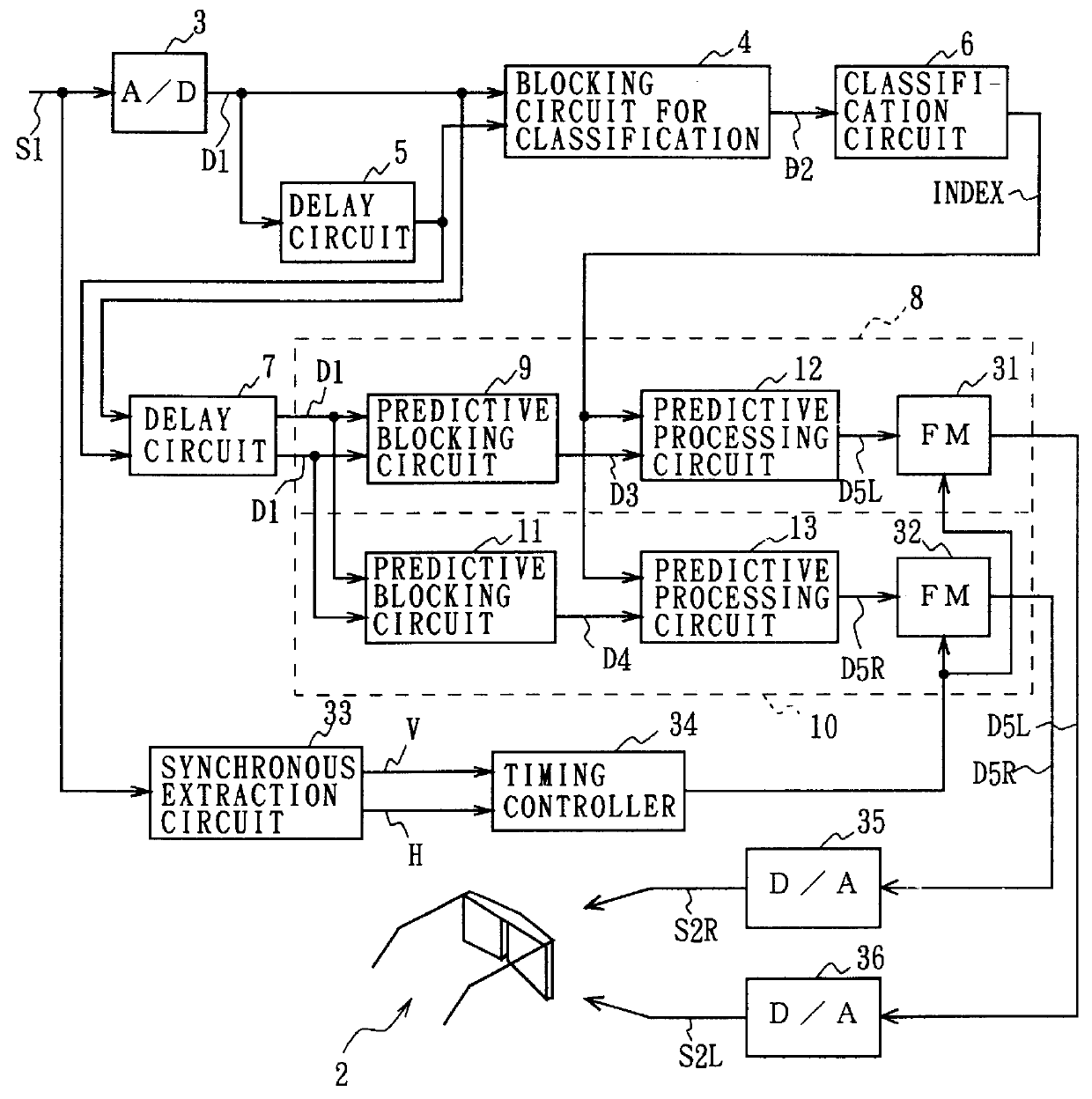
In FIG. 1, numeral 1 generally shows a stereoscopic viewing device. A video signal for left eye (hereinafter, this is referred to as a left-eye video signal) S2L and a video signal for right eye (hereinafter, this is referred to as a right-eye video signal) S2R having a parallax therebetween are generated from single input television signal S1. The image which is based on each of these left-eye video signal S2L and right-eye video signal S2R is displayed on a display device 2.

In this case, the stereoscopic viewing device 1 converts the received input television signal S1 into the television data D1, with the sampling frequency of 13.5 [MHz], by means of an analog-to-digital conversion circuit (A / D) 3. The television data D1 is directly supplied to a blocking circuit for classification 4 and also supplied to the blocking circuit for classification 4 via a delay circu...


PUM


Abstract

This invention concerns a stereoscopic viewing device and a stereoscopic viewing method, and makes it possible to provide a satisfactory stereoscopic image without increasing of the quantity of recorded information and the quantity of transmitted information. According to the invention, the input television signal is classified respectively on the basis of the level distribution pattern for every pixel in the spatio-temporal region whose center is lying on each attentional pixel, and the input television signal is blocked for every pixel in the spatio-temporal region whose center is lying on each attentional pixel respectively so as to generate the pixel data for predictive calculation, and the predictive calculation of the predictive calculating pixel data is processed utilizing the predictive coefficient which is corresponding to the result of classification obtained from the classifying means out of the predictive coefficients of each set which have been previously prepared, so as to generate the video signal for left eye and the image signal for right eye respectively, and then the stereoscopic image is displayed on the basis of the video signal for left eye and the video signal for right eye; in this way a stereoscopic image can be projected on the displaying means such that a flicker is eliminated and a deterioration of the image quality is prevented.

Description

1. Field of the InventionThis invention relates to a stereoscopic viewing device and a stereoscopic viewing method, and more particularly, is applicable to a stereoscopic viewing device for displaying a stereoscopic image based on the input television signal.2. Description of the Related ArtHeretofore, various stereoscopic viewing devices have been proposed, as published in, for instance, The Report of The Television Institute Vol. 45, No. 4, pp. 446-452 (1991).In these stereoscopic viewing devices, there are those in which two images having parallax, which are corresponding to the left eye and the right eye, are displayed on a television monitor in such a manner that they are alternately switched for each field, while the displayed image is observed through a liquid crystal shutter glasses of which left-eye shutter and right-eye shutter are opened and closed in a synchronized manner with switching of the displayed image, and hereby stereoscopic viewing is realized.By the way, in th...

Claims


Application Information

Patent Timeline
Patent Type & Authority Patents(United States)
IPC IPC(8): H04N13/00H04N13/239H04N13/243
CPCH04N13/0051H04N13/0055H04N13/0059H04N19/597H04N13/0048H04N13/0242H04N13/0438H04N13/044H04N13/0497H04N13/0239H04N13/341H04N13/167H04N13/243H04N13/344H04N13/194H04N13/189H04N13/161H04N13/239H04N13/398
Inventor NAKAYA, HIDEOKONDO, TETSUJIRO
Owner SONY CORP
Why Eureka
Try Eureka