Movement pattern recognizing apparatus for detecting movements of human bodies and number of passed persons

Inactive Publication Date: 2000-06-27
PANASONIC CORP
View PDF20 Cites 56 Cited by
  • Summary
  • Abstract
  • Description
  • Claims
  • Application Information

AI Technical Summary

Problems solved by technology

However, in the case where the number of persons is counted manually, a large cost and a complicated operation are required.
Thus, there arises a problem in that labor and time cannot be saved.
The mechanical detection method requires a large scale facility, the cost of which cannot be reduced.
What is worse, the method suffers from an excessively large space being required for installation.
What is worse, since whether or not all of the doorways are detected cannot be recognized, errors frequently occur in detection.
Thus, there arises a problem in that the number of per

Method used


Image

  • Movement pattern recognizing apparatus for detecting movements of human bodies and number of passed persons
  • Movement pattern recognizing apparatus for detecting movements of human bodies and number of passed persons
  • Movement pattern recognizing apparatus for detecting movements of human bodies and number of passed persons

Examples


first embodiment

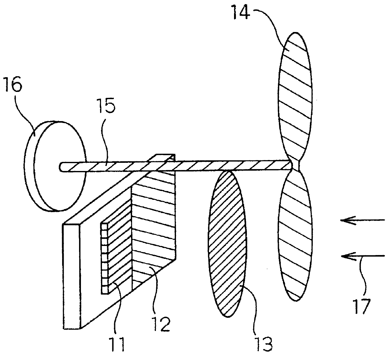
FIG. 1 is a perspective view showing a movement signal detection means for use in a movement pattern recognizing apparatus according to the present invention.

In general, as a sensor for use in an apparatus for detecting an infrared ray generating source, an infrared sensor or the like is employed. As the infrared sensor, two types have been known, one of which being a quantum type sensor for detecting the infrared rays as photons; and a residual one being a thermal sensor which uses change in the physical properties of a device occurring due to a thermal function in which the device absorbs infrared rays as electromagnetic waves and the temperature of the device is raised. Since the former sensor is generally required to be cooled with liquid nitrogen or the like, the latter thermal sensor is generally employed. Among the thermal sensors, pyroelectric infrared sensors exhibit superior excellent sensitivity and therefore the sensor of this type is suitable to detect the infrared ray ...

second embodiment

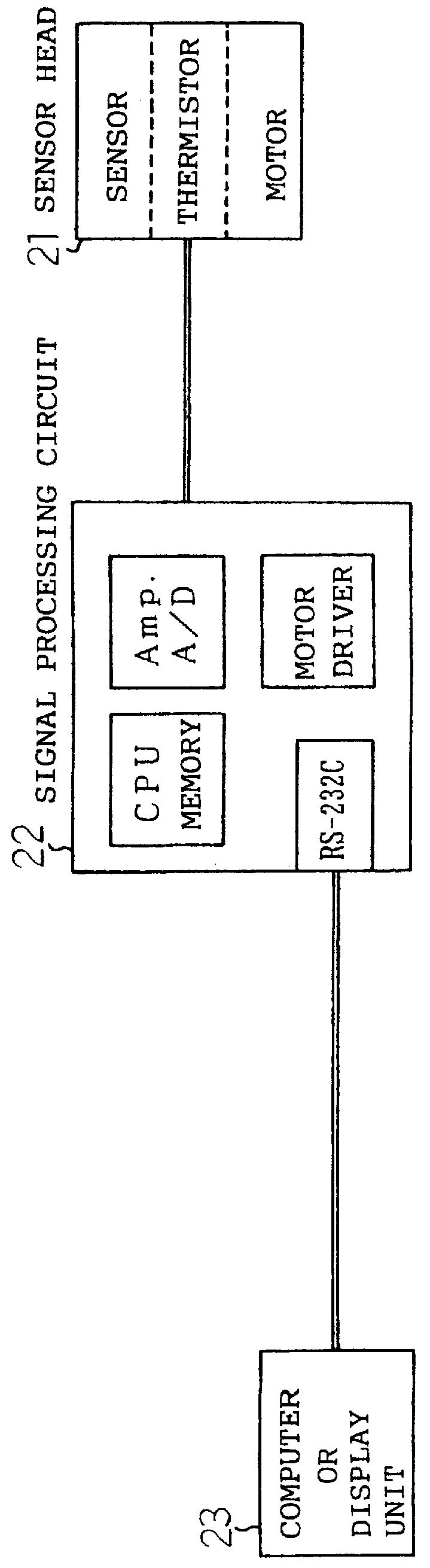
FIG. 2 is a structural view showing the movement pattern recognizing apparatus according to the present invention. A sensor head 21, which is the movement signal detection means, has the sensor shown in FIG. 1. Since the sensor head 21 has the plural and line-shape pyroelectric devices 11 shown in FIG. 1, consideration of an output value of each of the pyroelectric devices 11 at each time in such a manner that the plural pyroelectric devices 11 are made to be references enables the movement direction of the moving heat generating body on the plural pyroelectric devices 11 to be detected. The output from the sensor head 21 is supplied to a signal processing circuit 22 through a cable having a length of several meters. The signal processing circuit 22 includes an amplifying circuit (indicated as "Amp." shown in FIG. 2) and an A / D converter (indicated as "A / D" shown in FIG. 2). The output from the sensor head 21 supplied to the signal processing circuit 22 is amplified by the amplifyin...

third embodiment

FIG. 8 is a flow chart of the operation of the movement pattern recognizing apparatus according to the present invention. The structure and operation of the movement pattern recognizing apparatus according to this embodiment are similar to those according to the embodiment described with reference to FIGS. 1 to 7. The difference lies in the type of information of data about various movement patterns, the process of recognizing information to be performed after the movement pattern has been selected and obtained results. FIG. 9 shows specific binary-coded data about movement patterns realized when persons enter or leave the doorway. In the drawing, states are illustrated in which two persons overlap or successively pass the detection region. In this embodiment, the foregoing movement patterns are considered, and information indicating directions in which persons have passed through the detection region has been stored in the memory of the signal processing circuit 22 shown in FIG. 2 ...


PUM


Abstract

A movement pattern recognizing apparatus has a movement signal detection device including a sensor for detecting a mobile body in a detection region and for providing a movement signal indicating the position of the mobile body. The signal changes as time elapses. The apparatus further has a movement pattern storage device for storing data about previous movement patterns which were realized when a mobile body moved in the detection region, and a movement pattern selection device for selecting data about the movement pattern from the movement pattern storage device based upon the movement signal detected by the movement signal detection device.

Description

1. Field of the InventionThe present invention relates to a movement pattern recognizing apparatus using, for example, an infrared array sensor for detecting movement directions of human bodies and the number of persons who have passed through a doorway or the like and further relates to an apparatus for detecting movements of human bodies and an apparatus for detecting the number of passed persons.2. Related Art of the InventionIn recent years, security, control of air conditioning and illumination control have been required to measure a state where human beings existing in a room and temperature distribution in the same in order to detect whether a human being exists in the room and the amount of activities in the room. Moreover, companies and the like are required to perform control of persons who exist in a room so as to recognize and control the number of persons who have entered the room or a building and those who have left the same.As a conventional method of controlling the...

Claims


Application Information

Patent Timeline
IPC IPC(8): G06K9/00G07C9/00
CPCG07C9/00G06K9/00335G06V40/20
Inventor HASHIMOTO, KAZUHIKOYOSHIIKE, NOBUYUKIMATSUEDA, SATOSHIKAWAGUCHI, CHIHIRO
Owner PANASONIC CORP
Why Eureka
Try Eureka