Magnetic pole rotor for revolution counting

a technology of magnetic pole rotor and revolution counting, which is applied in the direction of instruments, devices using electric/magnetic means, dynamo-electric machines, etc., can solve the problems of inaccurate rotational speed measurement, motor vehicle no longer working, and having to be towed away, etc., to achieve accurate rotational speed measurement

Inactive Publication Date: 2000-07-11
DONNER MICHAEL
View PDF15 Cites 6 Cited by
  • Summary
  • Abstract
  • Description
  • Claims
  • Application Information

AI Technical Summary

Benefits of technology

The invention differs from the prior art in that the plastics ring is pressed firmly onto the base ring by the cage ring so that, in the event of high temperatures causing the strength of the plastics material to decrease, said plastics ring cannot be displaced in the peripheral direction on the shaft, even at high rotational speeds. This ensures accurate rotational speed measurement.

Problems solved by technology

These bring about very steep shift gradients when scanning.
False pulses of this type lead to the recognition of undefined driving conditions which result in disconnection of the controls, so that the motor vehicle is no longer operative and has to be towed away.
However, since the strength of the plastics material decreases at high operating temperatures of 200.degree. C., at high rotational speeds of several thousand revolutions per minute the magnetic pole gear can be displaced in the peripheral direction with respect to the shaft, with the result that it is no longer possible to measure the rotational speed accurately.

Method used


Image

  • Magnetic pole rotor for revolution counting
  • Magnetic pole rotor for revolution counting

Examples


Embodiment Construction

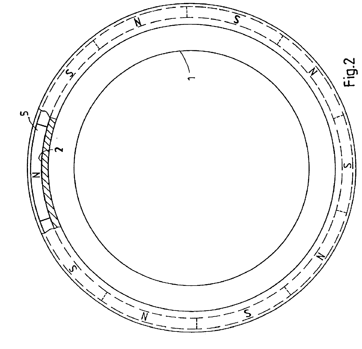
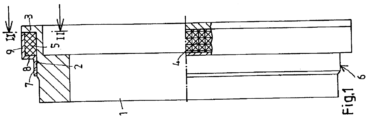
The magnetic pole rotor includes a base ring 1 of steel, ceramic or composite material, which is tensioned in the axial direction on a shaft whereof the rotational speed is to be measured, and can thus take up the high tensile force. The shaft can be the gear shaft of a motor vehicle. The base ring 1 has an outer cylindrical surface 2 which adjoins an outwardly directed annular wall 3. The cylindrical surface 2 is provided with a knurl-type profile 4.

A plastics ring 5 contains embedded magnetic poles whereof the orientation N, S is specified in FIG. 2. These can be magnetic parts inserted in an annular connection. Frequently, however, plastics rings 5 of this type are injection moulded parts. The magnetic poles are polarized in the desired manner. The plastics ring 5 is pressed onto the cylindrical surface 2, the knurl-type portion 4 ensuring a reliable seating. The strength of the plastics material is adversely affected at high temperatures. At high rotational speeds of several tho...


PUM


Abstract

PCT No. PCT/EP97/00152 Sec. 371 Date Jun. 2, 1998 Sec. 102(e) Date Jun. 2, 1998 PCT Filed Jan. 15, 1997 PCT Pub. No. WO97/26543 PCT Pub. Date Jul. 24, 1997A magnetic pole rotor having a plurality of magnetic poles which are arranged on a base ring. The technical problem is to construct the magnetic pole gear such that a non-rotational connection to the shaft remains assured, even at high operating temperatures. A plastics ring (5) surrounding the magnetic poles is pressed onto a cylindrical surface (2) of the base ring (1) and a cage ring (6) covers the plastics ring (5).

Description

The invention relates to a magnetic pole rotor having a plurality of magnetic poles which are arranged on a base ring.The field of application of the invention is the measurement of the rotational speed of shafts such as turbine shafts, generator shafts, machine shafts, drive shafts and the like. A particular field of application can be seen in automotive engineering in the case of gear shafts, speedometer shafts, crankshafts, camshafts, gears and the like.PRIOR ARTThe use of gearwheel-type rotors is known. These bring about very steep shift gradients when scanning. Consequently, rotary oscillations of the shaft can generate shift pulses and simulate rotational speed. False pulses of this type lead to the recognition of undefined driving conditions which result in disconnection of the controls, so that the motor vehicle is no longer operative and has to be towed away.DE 36 36039 A1 discloses magnetic pole gears of a plastics-bonded magnetic material which have a desired number of po...

Claims


Application Information

Patent Timeline
Patent Type & Authority Patents(United States)
IPC IPC(8): G01P3/487G01P3/42
CPCG01P3/487
Inventor DONNER, MICHAEL
Owner DONNER MICHAEL
Why Eureka
Try Eureka