Lateral electrode type spark plug with geometrical relationships with ground electrode

a technology of ground electrode and spark plug, which is applied in the direction of spark plugs, machines/engines, mechanical equipment, etc., can solve the problems of insufficient accelaration of the engine, loss of cold starting capability, and likely carbon fouling of the insulation nose of the insulation plug, so as to achieve effective protection of the ledge portion and high insulation resistance

Inactive Publication Date: 2000-07-18
NGK SPARK PLUG CO LTD
View PDF9 Cites 36 Cited by
  • Summary
  • Abstract
  • Description
  • Claims
  • Application Information

AI Technical Summary

Benefits of technology

to provide a semi-creeping discharge type spark plug which is capable of effectively protecting the ledge portion against the flashover even when the insulator nose is unacceptably carbon fouled, and further maintaining a high insulation resistance by facilitaing the self-cleaning action due to the creeping spark discharges.

Problems solved by technology

However, the insulator nose is likely to be carbon fouled especially when running the engine at the time of traffic congestion in winter seasons.
The flashover phenomenon prevents the spark discharges from normally running across electrodes, thus inviting inconveniences such as, for example, an engine stall, unstable idling, loss of cold starting capability and insufficient accelaration of the engine.
This substantially obviates the inconveniences such as an engine stall, unstable idling, incapability of cold starting and insufficient accelaration of the engine.

Method used


Image

  • Lateral electrode type spark plug with geometrical relationships with ground electrode
  • Lateral electrode type spark plug with geometrical relationships with ground electrode
  • Lateral electrode type spark plug with geometrical relationships with ground electrode

Examples


first embodiment

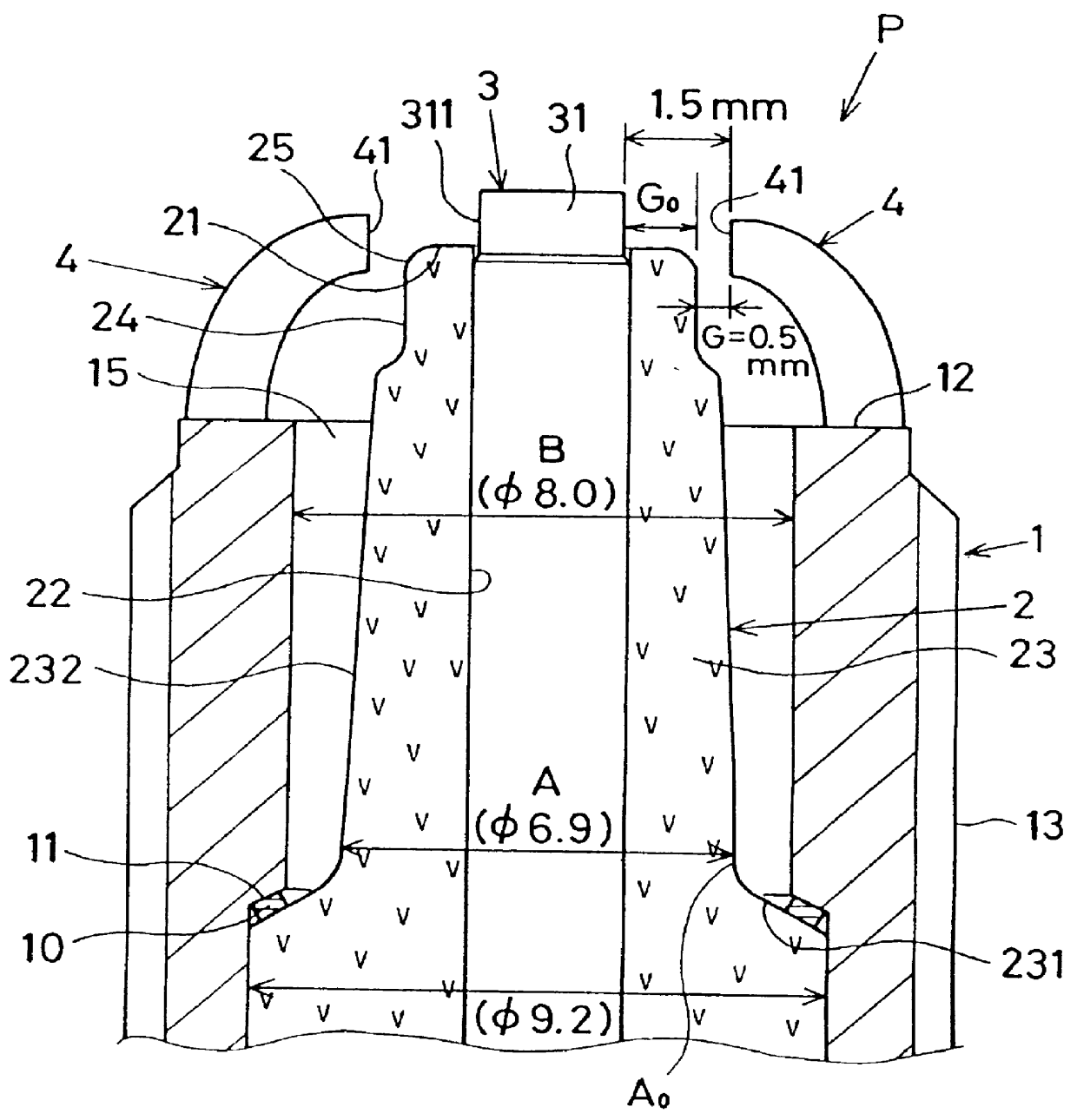
Referring to FIGS. 1, 2 and 17 which show a semi-creeping discharge type spark plug (P) according to the invention, the spark plug (P) has a cylindrical metal shell 1, an inner wall of which has a seat portion 11. Within the metal shell 1, a tubular insulator 2 is fixedly placed with a front end surface 21 of the insulator 2 extended beyond a front end surface 12 of the metal shell 1. The insulator 2 has an axial bore 22 in which a center electrode 3 is firmly supported. As designated by numeral 4, ground electrodes are welded to the front end 12 of the metal shell 1. A front end surface 41 of the ground electrodes 4 are bent to oppose an outer surface 311 of the center electrode 3 directly or by way of a front end section of the insulator 2.

An outer surface of the metal shell (low carbon steel) 1 has a male threaded portion (M14) 13 through which the spark plug (P) is to be mounted on a cylinder head of an internal combustion engine. An inner wall of the metal shell 1 has a diamete...

second embodiment

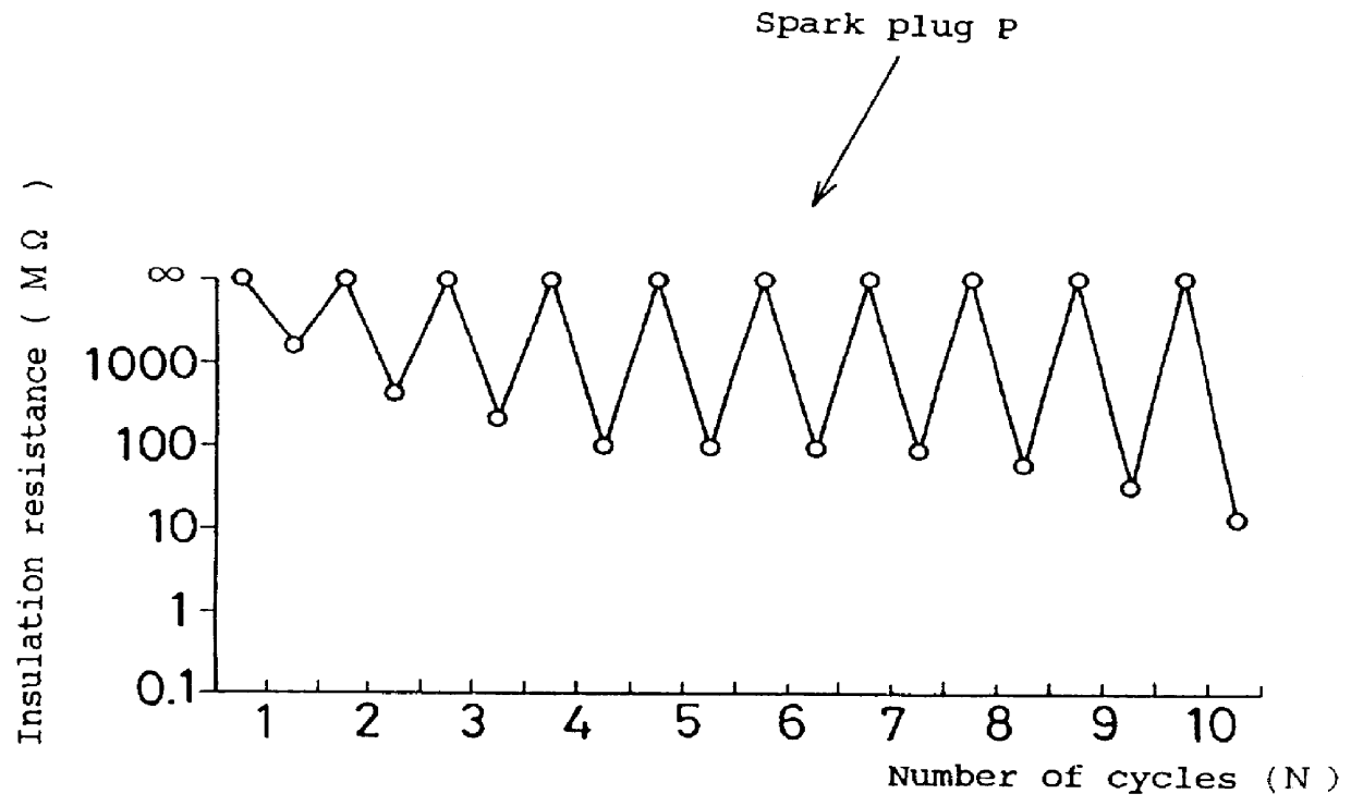
FIGS. 5 through 8 show the invention in which an intermittent creeping type spark plug (Q) is provided which is structurally identical to the semi-creeping discharge type spark plug (P) except that the front end of the ground electrode 4 is partly overlapped with the front end surface 21 of the insulator 2. The spark plug (Q) forms the spark discharge gap (Go=1.0 mm) between the front end surface 41 of the ground electrode 4 and the outer surface 311 of the center electrode 3 in order to effectuate the aerial spark discharges and intermittent creeping spark discharges therebetween. At the time when the insulator 2 is carbon fouled unacceptably, the ground electrode 4 releases the creeping spark discharges intermittently along the front end surface 21 of the insulator 2 across the air gap (G=0.5 mm) between a front edge portion 42 of the ground electrode 4 and the front end surface 21 of the insulator 2.

In the intermittent creeping type spark plug (Q), the inner wall of the metal she...

fourth embodiment

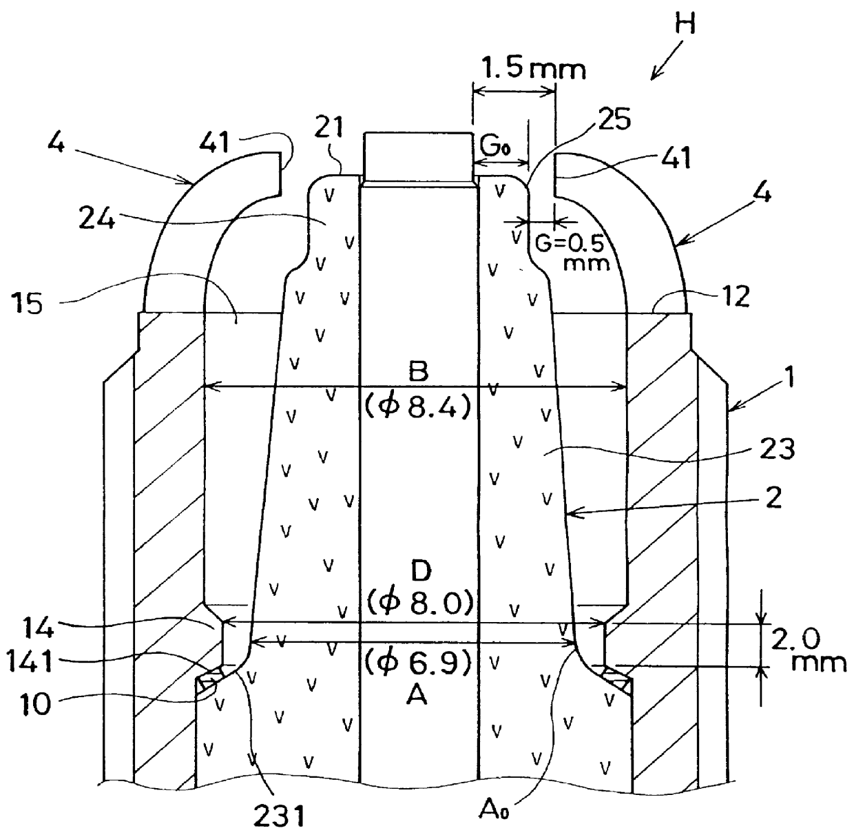
FIGS. 11 and 12 show the invention in which a semi-creeping discharge type spark plug (S) is provided which is generally identical to the semi-creeping discharge type spark plug (H) of FIG. 3 except for the following particulars.

In the spark plug (S) according to the fourth embodiment of the invention, the male threaded portion 13 is formed in terms of M12 which is smaller than the size of M 14. This may account for the presence of the ledge portion 14 provided on the inner wall of the metal shell 1. The inner diameter (B) of the metal shell 1 is 7.0 mm and the inner diameter (D) of the ledge portion 14 is 6.2 mm. The insulator 2 measures 5.9 mm in basal diameter (A) and 14.0 mm in length.

The insulator nose 23 has a tubular section 230a, the tapered shoulder portion 231 and the straight neck portion 24 which extends beyond the front end surface 12 of the metal shell 1.

In this instance, the insulator nose 23 has a forward edge 12f of the tubular section 230a which corresponds to the ...


PUM


Abstract

In a spark plug, a cylindrical metal shell (1) is provided whose inner wall has a rear section and a front section to respectively serve as a diameter-increased section and a diameter-decreased section with a seat portion (1) as a boundary therebetween. An insulator (2) is fixedly placed within the metal shell (1) so that a front end surface (21) of the insulator (2) extends beyond a front end surface (12) of the metal shell (1) with a shoulder portion (231) of an insulator nose (23) engaged against the seat portion (11) of the metal shell (1) by way of a packing (10). A center electrode (3) is fixedly placed within an axial bore (22) of the insulator (2), A ground electrode (4) is connected to the front end surface (12) of the metal shell (1), and bent so that a front end surface (41) of the ground electrode (4) opposes an outer surface (311) of the center electrode (3). The outer surface (311) and a front end surface (31) of the center electrode (3) are provided to respectively serve as a firing portion so as to form a spark discharge gap (Go) with the front end surface (41) of the ground electrode (4), the front end surface (41) of the ground electrode (4) forming an air gap (G) with an outer surface (25) of the insulator (2) so as to release creeping spark discharges along a front end surface (21) of the insulator (2).

Description

1. Field of the InventionThe invention relates to a spark plug mounted on an internal combustion engine, and particularly concerns to a spark plug which is improved to facilitate the self-cleaning action against the carbon-related deposit collected on an insulator.2. Description of Prior ArtIn a semi-creeping discharge type spark plug disclosed by e.g., U.S. Pat. No. 5,448,130, an air gap is formed between an outer surface of a center electrode and a front end surface of a ground electrode, and releasing creeping spark discharges along a front end surface of an insulator so as to facilitate the self-cleaning action.As an extension technique of the above spark plug, an intermittent creeping discharge type spark plug has been introduced in which a spark discharge gap is formed between an outer surface of the center electrode, and creeping spark discharges are released from an inner edge portion of a ground electrtode toward a front end surface of an insulator so as to facilitate the s...

Claims


Application Information

Patent Timeline
Patent Type & Authority Patents(United States)
IPC IPC(8): H01T13/32H01T13/20H01T13/52
CPCH01T13/20H01T13/32
Inventor MATSUBARA, YOSHIHIROKOKUBU, AKIOYOSHIDA, KAZUMASA
Owner NGK SPARK PLUG CO LTD
Why Eureka
Try Eureka