Disk control unit for holding track data in non-volatile cache memory

a track data and non-volatile technology, applied in the direction of electric digital data processing, instruments, computing, etc., can solve the problems of inability to report process failures, abnormal finishing, and the difference between the recording formats of input/output processing software and the disk uni

Inactive Publication Date: 2000-08-08
FUJITSU LTD
View PDF19 Cites 38 Cited by
  • Summary
  • Abstract
  • Description
  • Claims
  • Application Information

AI Technical Summary

Benefits of technology

The LTD holds a data length of an R0 record on the track as recording format information. When a format write command to change the recording format after an R1 record subsequent to the R0 record of the track data is received from the upper apparatus, the write cache control unit recognizes a start position of the R1 record from the data length of the R0 record in the LTD and can change the recording format on the cache memory. The LTD holds the number of records existing on the track as recording format information. Therefore, for the write request by the designation of the record number from the upper apparatus, the write cache control unit can discriminate whether the designated record exists on the track or not with reference to the number of records in the LTD. As recording format information, the LTD holds an equal length flag indicating that all of the records on the track have the same data length. Therefore, for the write request by the designation of the record number from the upper apparatus, the write cache control unit can calculate the position (address) of the designated record on the cache memory from the equal length flag and the record length and can write.
Further, a defective alternating track correspondence table indicative of the correspondence between the defective track and the alternating track is provided for the disk control unit. In this case, as recording format information, the LTD holds a defective track flag to recognize a defective track. When the defective track flag is recognized for the write request from the upper apparatus, the write cache control unit writes to the alternating track on the cache memory with reference to a defective alternating track correspondence table. As a cache memory, a non-volatile cache memory which can hold data when the power supply is shut off is provided and the LTD is stored in the non-volatile cache memory. Thus, the contents in the table of the LTD can be continuously held for the on / off operations of the power supply of the apparatus. The disk unit has an exclusive-use area for storing the contents of the LTD on a disk medium. Consequently, even if there is a rearrangement of the disk units or a movement of the disk units among the systems, the contents of the LTD can be effectively used.

Problems solved by technology

If the input / output processes are finished on the cache memory without confirming the recording format of the disk unit, there are various problems.
For example, although the input / output processes are executed by a one-sided instruction of a host computer, there is often a mistake in recognition of an input / output processing software, so that there is a situation such that a record of a format different from the recording format on the disk unit is written.
Such a difference between the recording formats of the input / output processing software and the disk unit occurs due to an error that is caused by a bug of the input / output processing software.
In addition to such an error, however, there is also a case where the input / output processing software purposely changes the last recording format, thereby finishing abnormally.
However, in the cache control such that the end of the input / output process is notified to the host computer at a time point when the write data to the record has been written into the cache memory, there occurs a problem such that even if the recording format of the disk unit differs from the recording format written into the cache memory, such a fact cannot be recognized and a failure of the processes cannot be reported.
As another example, in a reading or searching process of the disk unit, since data has an uncertain length, unless the records of the track are sequentially read out, it is impossible to access a target track, and the processes on the cache memory cannot be finished.

Method used


Image

  • Disk control unit for holding track data in non-volatile cache memory
  • Disk control unit for holding track data in non-volatile cache memory
  • Disk control unit for holding track data in non-volatile cache memory

Examples


Embodiment Construction

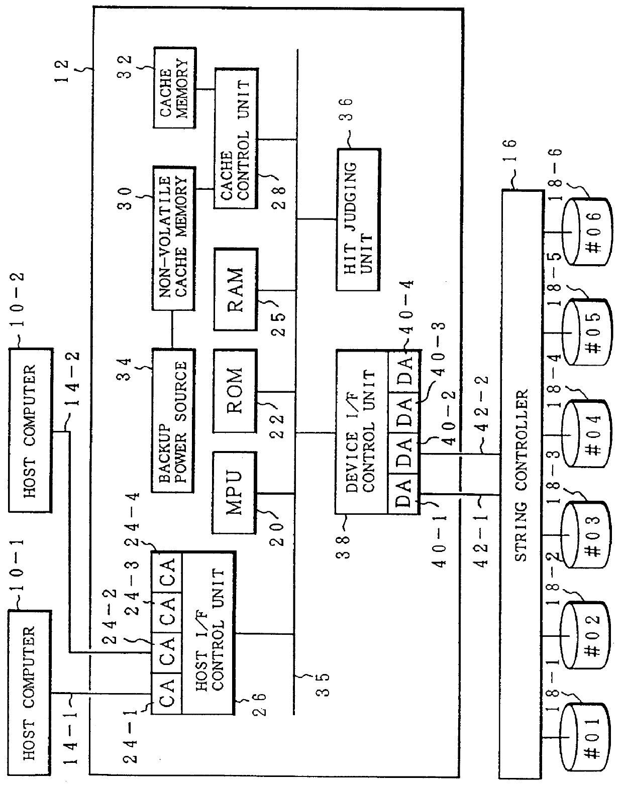
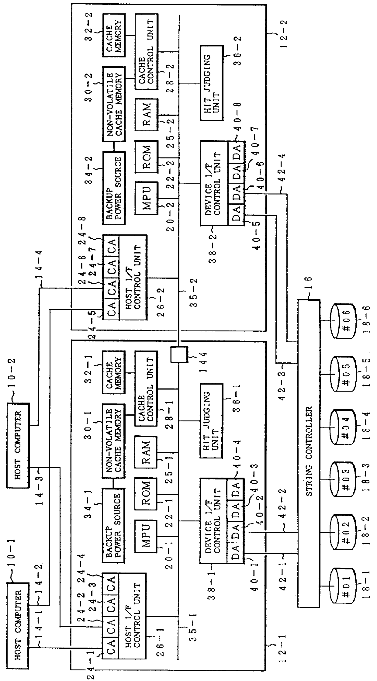
FIG. 1 shows a construction of a magnetic disk subsystem to which the invention is applied. In the embodiment, a disk control unit 12 is provided for two host computers 10-1 and 10-2. Six disk units 18-1 to 18-6 are connected through a string controller 16 under the domination of the disk control unit 12. The disk units 18-1 to 18-6 have device Nos. #01 to #06. An MPU 20 is provided for the disk control unit 12. A ROM 22, a RAM 25, a host interface control unit 26, a cache control unit 28, a hitjudging unit 36, and a device interface control unit 38 are connected to the MPU 20 through an internal bus 35. In the embodiment, four channel adapters (CA) 24-1 to 24-4 are provided for the host interface control unit 26. Among them, the channel adapter 24-1 is connected to the host computer 10-1 by a channel bus 14-1. The channel adapter 24-2 is connected to the host computer 10-2 by a channel bus 14-2. Four device adapters 40-1 to 40-4 are provided for the device interface control unit 38...


PUM


Abstract

A disk control unit for writing and reading data to / from at least one disk device on the basis of an input / output request of an upper apparatus includes a volatile cache memory for holding data of the disk device, a non-volatile cache memory and a recording format information table stored in the non-volatile cache memory for holding recording format information of the tracks of the disk device. A write cache control unit refers to the recording format information table so as to enable the upper apparatus to perform a writing process on the volatile cache memory even when corresponding data of the disk device do not exist on the volatile cache memory.

Description

BACKGROUND OF THE INVENTIONThe present invention relates to a disk control unit for writing and reading data to / from a disk apparatus having a data format of a variable length on the basis of an input / output request of an upper apparatus and, more particularly, to a disk control unit for holding data in a cache memory on a track unit basis, thereby promptly coping with an access from the upper apparatus.In recent years, in a magnetic disk subsystem which is used for an external storage of a computer system, it is indispensable to use a cache technique in a disk control unit to which a plurality of magnetic disk units are connected as physical devices under the domination of the disk control unit. Such a cache function of the disk control unit is known as a disk cache. In association with an access of a large quantity of data, there have been proposed various methods such as increase in capacity of the cache memory, formation of a non-volatile cache memory in order to guarantee the h...

Claims


Application Information

Patent Timeline
Patent Type & Authority Patents(United States)
IPC IPC(8): G06F12/16
CPCG06F12/16
Inventor KUMASAWA, TADASHITAKAHASHI, HIDEHISA
Owner FUJITSU LTD
Why Eureka
Try Eureka