Monitoring alarm systems

a monitoring and alarm system technology, applied in the field of alarm systems and detectors or peripheral devices, can solve the problems of dc smoke detectors being considerably more expensive, if added to the system, and the loop cannot distinguish a "trouble state"

Inactive Publication Date: 2000-08-15
LUQUETTE MARK H
View PDF13 Cites 15 Cited by
  • Summary
  • Abstract
  • Description
  • Claims
  • Application Information

AI Technical Summary

Problems solved by technology

Such loops cannot distinguish a "trouble state" from an "alarm state" as both conditions produce the same result, namely, opening the loop.
The DC smoke detectors are considerably more expensive and if added to the system will add substantial cost.
There are, however, two problems with that approach.
1. Conventional relays would not be able to be powered by minimal battery power should the AC power fail.
Furthermore, the circuit should be fail-safe, which means that failure of any component in the circuit would result in opening of the alarm loop.
Thus, this embodiment does not allow the central alarm panel to distinguish an "alarm state" from a "trouble state."

Method used


Image

  • Monitoring alarm systems
  • Monitoring alarm systems

Examples


Embodiment Construction

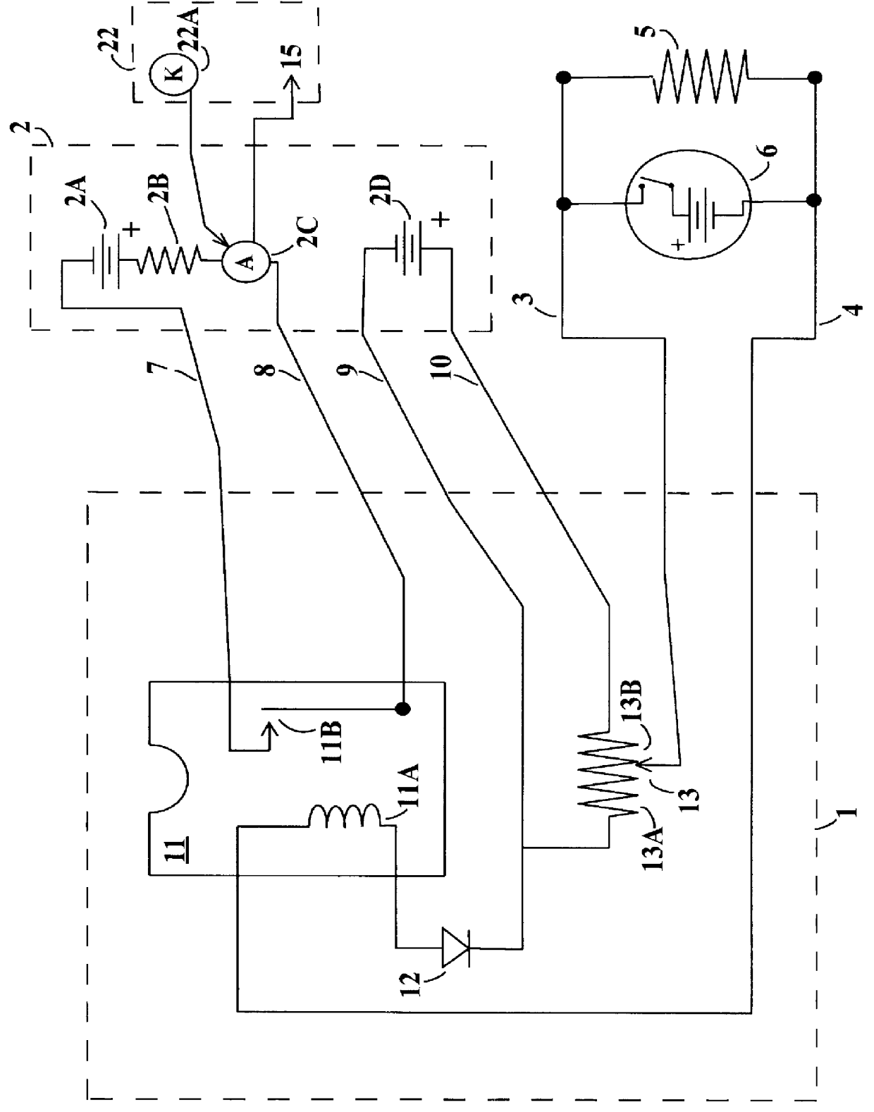
Referring now to FIG. 1, the fail safe Sensitive Monitor And Signaler for interconnect lines of AC powered smoke alarms with battery backup (SMAS) circuit 1 interfaces with an external source of power 9,10 and two electronic loops--an alarm loop 7,8 and an interconnect loop 3,4,5.

The power and alarm loops come from a central alarm system panel 2. The power is DC and typically is supplied at 2D either from an electronic DC power supply or by a battery. The alarm loop, originating at 7,8 comprises a direct current source 2A, a current limiting series resistor 2B, and a current monitoring device 2C. Current in the loop 7,8,11B thus is limited in the panel 2, which is programmed to expect the loop to be normally closed at 11B. The processing is done using the keys 22A on the key pad 22. When the alarm loop 7,8,11B is open, the alarm system circuitry 2C in the panel 2 recognizes an "alarm state" and signals the user by turning on a horn a other audible or visible signaling device 15 show...


PUM


Abstract

Typical apparatus according to the present invention for detecting a predetermined type of condition (such as the presence of smoke) at a given location and providing an indication (typically audible and/or visible) of the presence of such condition, comprises an electrical detector responsive to the type of condition, for providing a potential difference of at least a predetermined amount between two predetermined points; first circuitry for connecting at least a substantial fraction of the potential difference to an electrical relay or relay analogue in the apparatus so as to provide a predetermined first indication; and second circuitry responsive to a condition in the detector or in the first circuitry that is outside of a predetermined range, and thus of possible detriment to the optimum performance of the apparatus, to provide a predetermined indication. Typically the first circuitry provides one indication concerning the presence or absence of smoke and the second circuitry provides a different indication concerning the presence or absence of possible trouble in the apparatus.

Description

1. Field of the InventionThis invention relates to alarm systems and detectors or peripheral devices such as those that connect smoke alarms to central alarm panels. It has to do typically with fail safe sensitive monitors and signalers for interconnect lines of AC-powered smoke alarms with battery backup.2. Description of the Prior ArtAlarm systems often contain multiple sensors including smoke detectors, heat detectors, motion detectors, and switches that determine the open or closed state of a door or window. In some systems the individual sensors or a plurality of sensors are monitored by the system using one or more electronic loops, and the system sounds an alarm when one of the sensors is triggered. Such systems and loops are discussed in the prior art (U.S. Pat. Nos. 4,141,007; 4,144,528; 4,162,489; 4,176,346; 4,517,555; 4,191,946; 4,586,028; 4,745,398). In other types of alarm systems, the sensors themselves may contain alarm horns. Such devices may be standalone devices or...

Claims


Application Information

Patent Timeline
Patent Type & Authority Patents(United States)
IPC IPC(8): G08B29/18G08B29/00G08B25/04G08B25/01
CPCG08B25/04G08B29/181
Inventor LUQUETTE, MARK H.
Owner LUQUETTE MARK H
Why Eureka
Try Eureka