

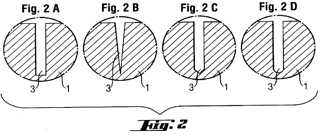
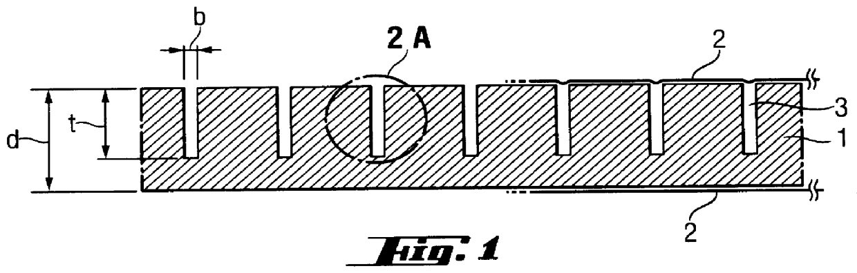
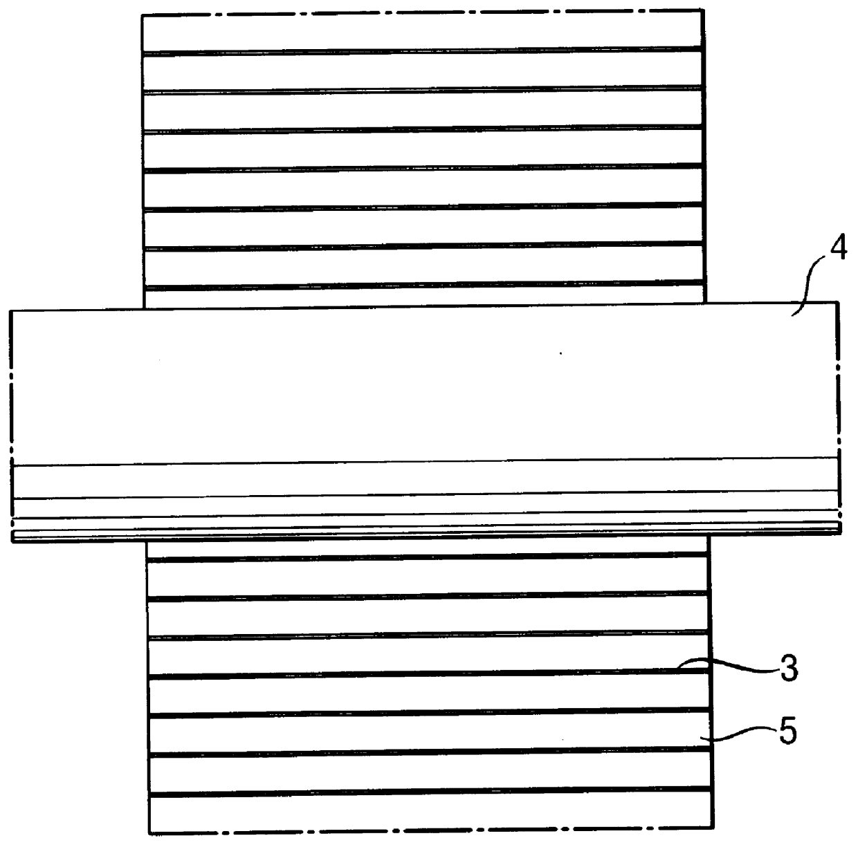
Panel-shaped, evacuated molded element, method of thermal insulation and use of the molded element
a technology of molded elements and molded elements, which is applied in the field of panel-shaped, evacuated molded elements, methods of thermal insulation and use of molded elements, can solve the problems of incomplete thermal insulation, large force required to make molded elements, and insufficient coverage of surfaces, so as to reduce heat loss, reduce heat loss, and increase the volume of molded elements
- Summary
- Abstract
- Description
- Claims
- Application Information
AI Technical Summary
Benefits of technology
Problems solved by technology
Method used
Image

Examples
example 2
A pipe carrying hot medium of up to several hundred degrees is sheathed with three layers of evacuated panels, each of which is welded within a gastight multilayer film and has a lamellar structure incorporated on its surface. Each panel has a thickness of 12 mm, and the joints are staggered at the ends of the panels and around the circumference. Each individual layer is fixed with adhesive tape. During use, the first layer is thermally decomposed on account of the temperature resistance of the sheathing film so that the vacuum is destroyed, and the sealing effect is increased thereby. On account of the thermally insulating effect of the first layer, the sheathing of the next layers is preserved intact, which produces an optimum insulating effect on account of the particularly good thermally insulating effect of the evacuated systems.
PUM
| Property | Measurement | Unit |
|---|---|---|
| Fraction | aaaaa | aaaaa |
| Width | aaaaa | aaaaa |
| Width | aaaaa | aaaaa |
Abstract
Description
Claims
Application Information