

Ozone dispensing system
a technology of ozone gas and dispensing system, which is applied in the direction of oxygen/ozone/oxide/hydroxide, medical devices, inorganic chemistry, etc., can solve the problems of difficulty for operators to judge the back-pressure of veins, tiresome for operators to maintain a steady pressure on the plunger of syringes, and ozone concentrations that vary from the preset valu
Inactive Publication Date: 2000-08-29
DUNDER OVE KARL
View PDF7 Cites 51 Cited by
- Summary
- Abstract
- Description
- Claims
- Application Information
AI Technical Summary
Benefits of technology
Operator fatigue, caused by the long steady pressure on the plunger of the syringe, is eliminated since the system is automatic.
Problems solved by technology
This has the disadvantage that the back pressure produced inside the ozone generator by the plunger of the syringe will cause the ozone concentration to vary from the preset value.
The valves inside the veins will close down if excessive ozone gas pressure is applied and it is difficult for the operator to judge the back-pressure from the vein.
It is very tiresome for the operator to maintain a steady pressure on the plunger of the syringe for the 10 to 20 minutes that are required to dispense the typical ozone-gas volume used for therapeutic treatment.
(a) The ozone dispense systems heretofore known, use a flow controller in line with the ozone generator to maintain the ozone gas flow rate at a constant value. When a syringe is filled by connecting it in line with the flow controller and the ozone generator, the back pressure produced inside the ozone generator by the plunger of the syringe will cause the ozone concentration to vary from the preset value.
(b) The ozone gas dispense rate is subject to the variations of the manually applied pressure to the plunger of the gas-filled syringe by the medical operator.
(c) The ozone gas dispense pressure is subject to the variations of the manually applied pressure to the plunger of the gas-filled syringe by the medical operator.
(d) The operator will suffer fatigue in his hand from maintaining a steady pressure on the plunger of the syringe for an extended period of time.
Method used
View moreImage
Smart ImageViewing Examples

Examples
example
The ozone dispense system described herein can be utilized to accurately maintain, and dispense ozone. As an example, the system can be set at the following:
______________________________________ Rate of Delivery 0 to 200 ml / min Concentration 0 to 50 micro grams O.sub.3 / ml O.sub.2 Flow controller can run at up to 200 ml / min Dispense Pressure up to 1.5 psi ______________________________________
Login to View More PUM
| Property | Measurement | Unit |
|---|---|---|
| concentration | aaaaa | aaaaa |
| pressure | aaaaa | aaaaa |
| volume | aaaaa | aaaaa |
Abstract
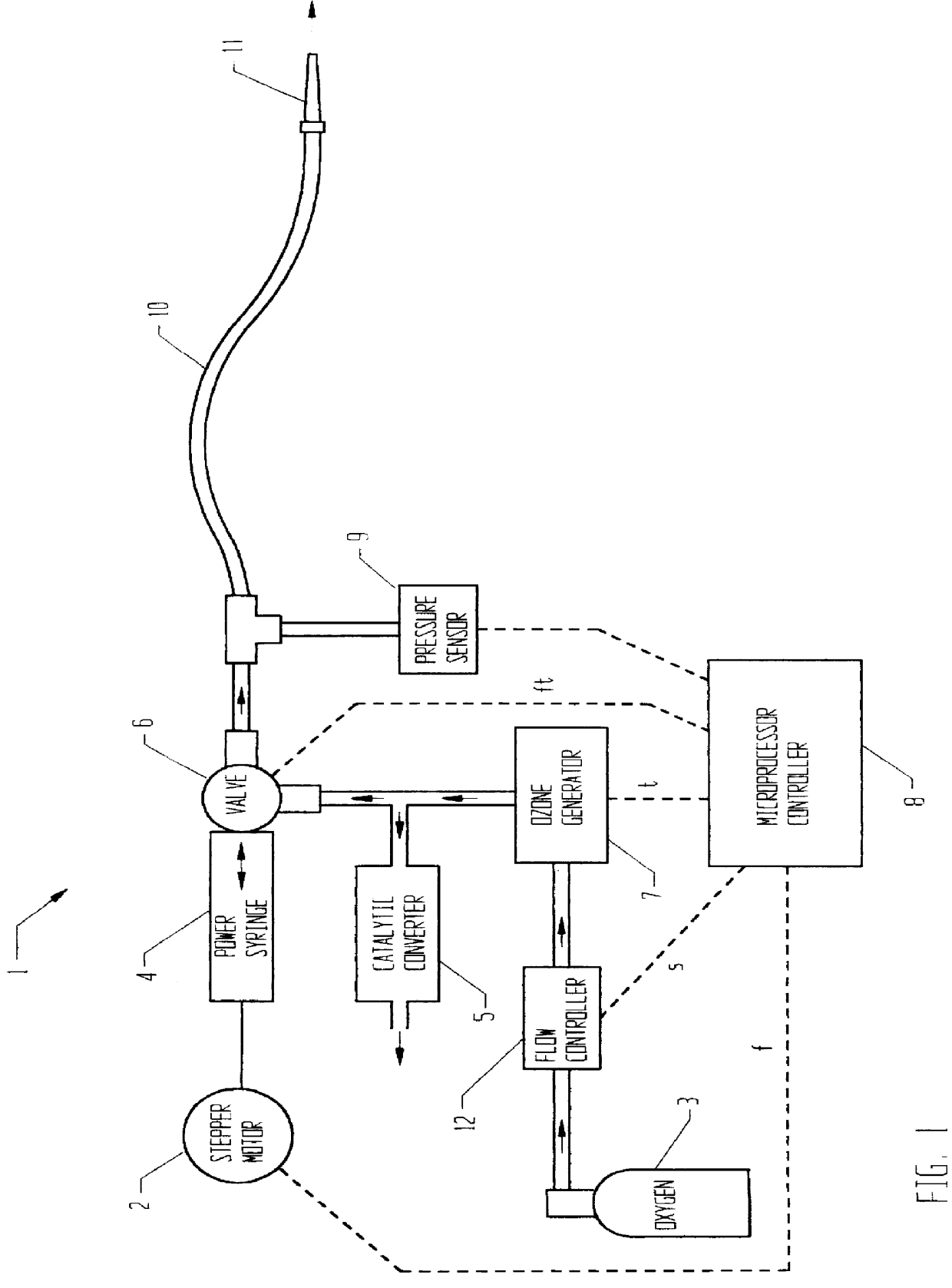
An ozone dispensing system comprising an ozone gas generating means, electrical means to control the concentration of ozone produced by said ozone gas generating means, means to control the concentration of ozone in a preset dispensed volume, an oxygen supply and venting means disposed between said ozone gas generating means and said dispensing of said ozone, said venting means for continuous venting of said ozone.
Description
FIELD OF INVENTIONThis invention relates to improvements in the dispensing of ozone gas for therapeutic purposes.BACKGROUND OF INVENTIONWhen ozone is used for therapeutic purposes, it is necessary to precisely control the dispensed ozone concentration, volume, pressure and rate of delivery.It is common that ozone dispense systems heretofore known, use a flow controller in line with the ozone generator to maintain the ozone gas flow rate at a constant value. When a syringe is used for direct gas injections into the veins of a patient, it is filled by connecting it in line with the flow controller and the ozone generator. This has the disadvantage that the back pressure produced inside the ozone generator by the plunger of the syringe will cause the ozone concentration to vary from the preset value.The rate at which ozone gas is dispensed directly into a vein of a patient is controlled by the manually applied pressure to the plunger of the gas-filled syringe. The ozone gas dispense ra...
Claims
Login to View More Application Information
Patent Timeline
 Patent Type & AuthorityPatents(United States)
IPC IPC(8): C01B13/11C01B13/10A61M5/00A61M5/31A61M5/48G05D7/06G05D11/13G05D16/20
CPCC01B13/10C01B13/11C01B2201/90
InventorDUNDER, OVE KARL
OwnerDUNDER OVE KARL