Radial taper tool for compressing electrical connectors

a technology of radial taper and connector, which is applied in the direction of manufacturing tools, insulating conductors/cables, shaping tools, etc., can solve the problems of difficult opening, failure of the tool to hold the thin-walled portion of the connector, and difficulty in extracting the connector from the tapered die after the compression cycl

Inactive Publication Date: 2000-09-05
RIPLEY TOOLS
View PDF26 Cites 57 Cited by
  • Summary
  • Abstract
  • Description
  • Claims
  • Application Information

AI Technical Summary

Benefits of technology

Bearing in mind the problems and deficiencies of the prior art, it is therefore an object of the present invention to provide a radial taper tool which is light in weight, has low material cost, and is not subject to distortion during the compression operation.
In another aspect, the plunger includes an enlarged plunger head for restricting retracted motion of the plunger.

Problems solved by technology

One problem with this type of design has been the difficulty of extracting the connector from the tapered die after the compression cycle.
In this type of design, the compressed connector can be so deeply forced into the die that it locks the two die halves together, making it difficult to open them.
Another problem with prior art tools is the failure of the tool to hold the thin-walled portion of the connector in alignment with, and squarely perpendicular to, the plunger portion of the tool which provides the compression force.
When correct alignment is not maintained, the connector will not be compressed properly, and may jam in the tapered cavity.
It is particularly difficult to keep the back straight and still keep the frame light, because the back portion of a C-frame is under a relatively high bending moment and is partially in compression and partially in tension.
Such distortion lets the two arms of the C-frame move away from parallel resulting in an improperly compressed connector that may fail, or which may jam in the die.
Making the C-frame stiffer usually requires more weight which adds cost and is undesirable for the user who may have to lift and carry the tool tens of thousands of times during its life.
A further problem with prior art tool designs has been the "full-cycle" ratchet mechanism.
This is advantageous for ensuring that a full stroke is applied to the tool handles to fully complete each compression operation, but it creates a problem when the tool operator discovers that a connector is misaligned and is about to jam in the die cavity.
This is inconvenient, and may tempt the operator to try to complete the compression cycle, jamming the connector more deeply and worsening the problem.
Another problem with prior art tools has been the adjustment mechanism.
Tool wear causes this distance to change.
Prior art tools have provided a single adjustment to the plunger to compensate for such wear, but the adjustment is difficult.
Yet another problem with prior art devices relates to the interconnection between the handle providing the compression force and the plunger performing the compression.

Method used


Image

  • Radial taper tool for compressing electrical connectors
  • Radial taper tool for compressing electrical connectors
  • Radial taper tool for compressing electrical connectors

Examples


Embodiment Construction

)

In describing the preferred embodiment of the present invention, reference will be made herein to FIGS. 1-3 of the drawings in which like numerals refer to like features of the invention.

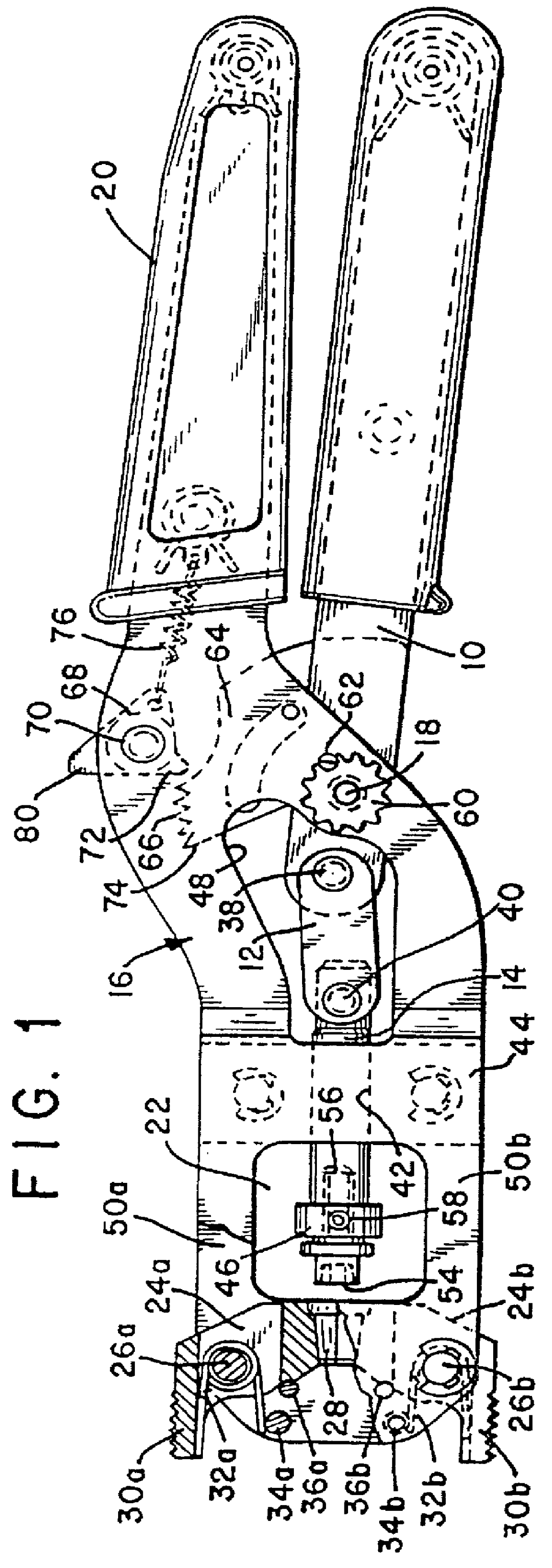
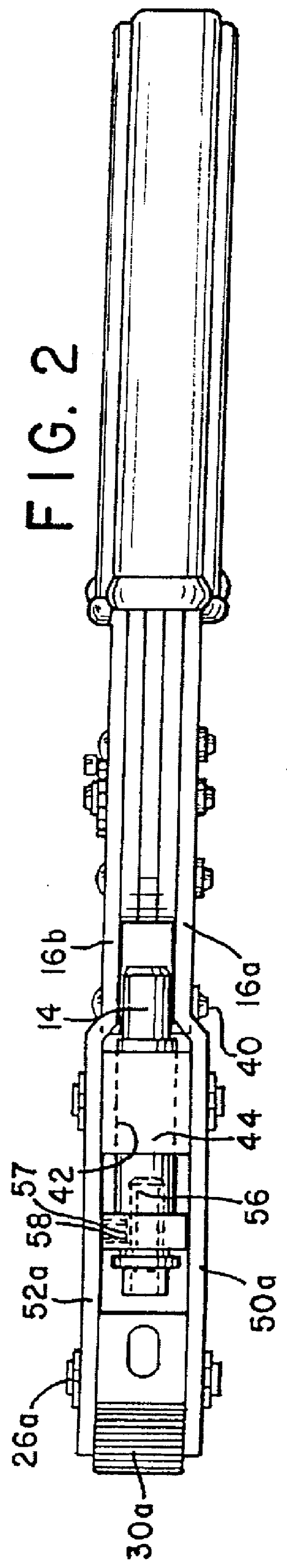
Referring to FIG. 1, the radial taper tool of the present invention comprises a lever handle 10 connected to a link 12 driving a plunger 14. The lever handle 10 is pivotally attached to an O-frame body 16 via pivot 18. O-frame body 16 is formed of a pair of opposed O-frame sidewalls 16a, 16b (see FIG. 2), and pivot 18 is mounted between them.

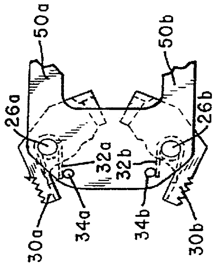
A body handle 20 is fixed relative to the body 16. The "O" in the O-frame body 16 defines a compression region 22 into which the connector and cable is inserted by opening die halves 24a and 24b (see FIG. 3). The die halves 24a, 24b are pivoted around corresponding die pivots 26a, 26b which extend between the two opposed O-frame sidewalls 16a, 16b. The die halves 24a, 24b are provided with a tapered cavity 28 that is axially aligned with the plunger 14 when the...


PUM

PropertyMeasurementUnit
tensionaaaaaaaaaa
distanceaaaaaaaaaa
conductiveaaaaaaaaaa

Abstract

A tool for attaching a connector to an end of a cable by compressing the connector axially and driving it into a tapered cavity uses a light rigid O-frame. The tapered cavity is formed in a pair of die halves which are both pivoted to the frame and which are provided with oppositely mounted handles, allowing the dies to be opened by squeezing the handles together. Two different adjustment means are provided and the tool is provided with a full-cycle ratchet mechanism to ensure complete compression of the connector during each use.

Description

1. Field of the InventionThis invention relates to tools for attaching connectors to coaxial cables. More specifically, this invention relates to tools which deform a thin-walled portion of the connector into a uniform circumferential seal around the cable by driving the connector in a direction parallel to the axis of the cable into a conically tapered cavity in a die to produce a radially tapered crimp.2. Description of Related ArtA common type of electrical connector used on coaxial cables includes a thin-walled cylindrical portion at the end of the connector which receives the cable. The coaxial cable is prepared by removing insulation and exposing the inner conductor and the outer conductive braid. The prepared cable is then inserted into the thin-walled cylindrical portion at the back end of the connector, and the thin-walled portion is radially compressed around the cable with a hand tool.The compression operation simultaneously connects the outer connector housing to the out...

Claims


Application Information

Patent Timeline
Patent Type & Authority Patents(United States)
IPC IPC(8): B25B27/02B25B27/10H01R43/042H01R43/04
CPCB25B27/10H01R43/0425H01R43/042Y10T29/49185Y10T29/53235Y10T29/49181Y10T29/49123Y10T29/53257Y10T29/53226Y10T29/539
Inventor TARPILL, ANDREW J.
Owner RIPLEY TOOLS
Why Eureka
Try Eureka