Thumb and fingernail polish remover device

a finger and nail polish technology, applied in the field of finger and nail polish removal devices, can solve the problems of limiting the use of sponge products in beauty salons

Inactive Publication Date: 2000-09-12
WALKER ALVIN M
View PDF7 Cites 21 Cited by
  • Summary
  • Abstract
  • Description
  • Claims
  • Application Information

AI Technical Summary

Problems solved by technology

There are health reservations about the use of sponge product in beauty salons because of the occurrence of bacterial collection and growth in the sponge.
This frequently occurs due to job rel

Method used


Image

  • Thumb and fingernail polish remover device
  • Thumb and fingernail polish remover device
  • Thumb and fingernail polish remover device

Examples


Embodiment Construction

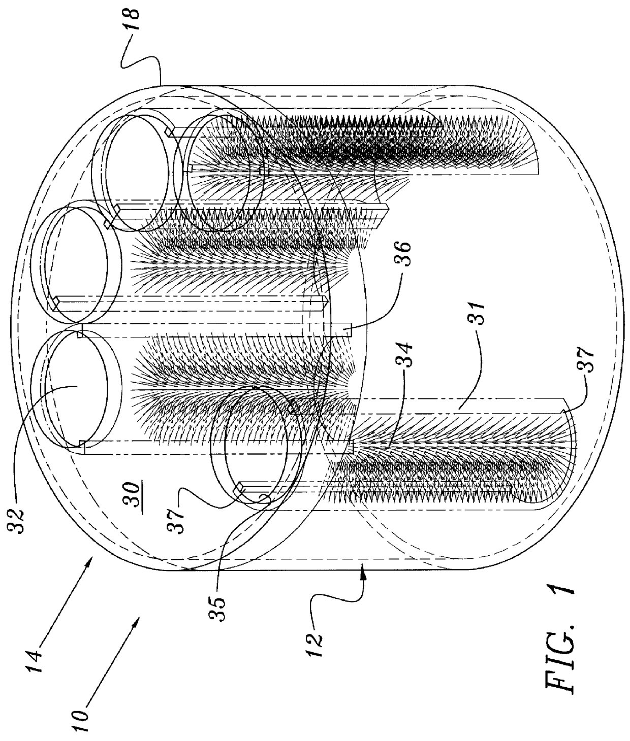
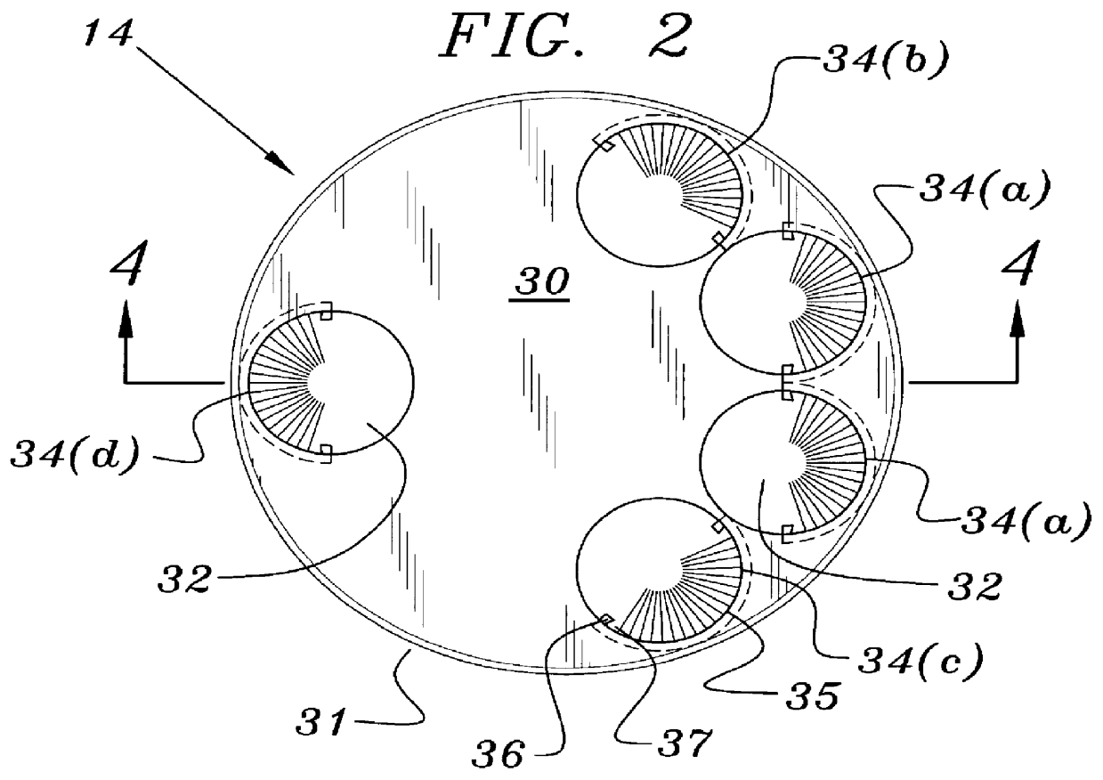
The preferred embodiment and the best mode of the present invention is shown in FIGS. 1 through 4. As shown in the Figures, the inventive nail polish remover device is generally designated by the numeral 10 and comprises three basic pieces or parts: a cylindrical container 12, a finger support and brush insert 14 having an integrally molded top disk shaped support 30 with a plurality of downwardly projecting arcuate or semicylindrical finger and brush support members 34 and a threaded cap 18. The container 12 has a cylindrical wall 20 secured to base 19. The cylindrical wall forms a circular opening at the top or proximal end of the container 12 thereby allowing insertion of the finger and brush insert 14. The exterior outer surface of the cylindrical wall 20 is formed with threads 22 which engage and hold cap 18. The interior wall surface 21 of the cylindrical wall 20 can be provided with an annular insert groove 26 to receive a rib (not shown) on the disk shaped support member or ...


PUM


Abstract

A nail polish remover device adapted for removing fingernail polish from all the fingers and thumb on a hand comprising a cylindrical receptacle defining a chamber with a brush insert assembly mounted within the chamber. The brush insert assembly defines a plurality of finger holes with adjacent semicylindrical support members to receive bristle members which are mounted in the semicylindrical support members allowing the finger and thumb of a user to remove nail polish from the users fingernails.

Description

1. Field of InventionThe present invention relates to devices for removing fingernail polish and in particular is directed towards a molded container with an insert having insertable one piece molded member with individual semicylindrical finger and thumb brush retainer and support members. Each brush retainer and support member holds a bristle assembly for removing fingernail polish simultaneously from the thumb and fingers of either hand.2. Description of the Prior ArtThe prior art contains many references directed to nail polish removal receptacles which support or suspend an insert structure to aid in the removal of hardened nail polish from fingernails after a finger has been immersed in nail polish remover contained within the receptacle. U.S. Pat. Nos. 4,474,195; 4,440,181; and 4,282,891 disclose nail polish remover devices in which a receptacle is provided with a sponge or sponge-like absorbent member insert. The sponge member insert is formed with an aperture forming a fing...

Claims


Application Information

Patent Timeline
IPC IPC(8): A45D29/00
CPCA45D29/007
Inventor WALKER, ALVIN M.
Owner WALKER ALVIN M
Why Eureka
Try Eureka