Corn processor for forage harvester

a forage harvester and corn processor technology, applied in agriculture, agriculture tools and machines, solid separation, etc., can solve the problems of kernel cracking, corn kernel proportions are cracked, and the cost of self-propelled forage harvesters is high

Inactive Publication Date: 2000-09-12
FISHER JR GIDEON A +1
View PDF17 Cites 15 Cited by
  • Summary
  • Abstract
  • Description
  • Claims
  • Application Information

AI Technical Summary

Benefits of technology

An object of this invention is to provide a corn processor unit or kit that can be built into a pull-type forage harvester so that such harvester can be used to properly harvest corn as well as hay crops.
Another object of the invention is to provide a simplified corn processor unit wherein chopped corn is delivered directly into the bite of two processor rolls with no intermediate structure between the cutterhead knives and the rolls, whereby there is less chance of the unit plugging.
Another object of this invention is to provide a corn processor having an upper roll closely adjacent to the cylinder generated by knives on a cutterhead and having a surface travelling counter to the travel of the cutterhead knives to strip material off of the knives and feed it into the bite between itself and an associated lower roll. The location of the upper roll and its aggressive stripping of the cutterhead allows the operator to set the harvester to cut the corn crop long and without producing plugging of the crop at the bite of the processor rolls.
A still further object of this invention is to provide a corn processor kit construction that can be added to or removed from a pull-type forage harvester without substantial design changes in the harvester.

Problems solved by technology

However, in harvesting corn, the stalks, leaves and ears of corn are fed with a cutterhead and only a portion of the corn kernels are cracked in the chopping operation.
When the kernels are passed between the rolls, the kernels are cracked.
A self-propelled forage harvester is expensive.
The cost is beyond what many farmers can afford.
However, generally corn processors have not been provided with pull-type machines.
If a pull-type machine is used to harvest corn without processing the kernels, the feed value is limited.
When an auger or other conveyor operates to convey the crop in the trough, there is a tendency to throw the material upwardly and out of the trough.

Method used


Image

  • Corn processor for forage harvester
  • Corn processor for forage harvester
  • Corn processor for forage harvester

Examples


Embodiment Construction

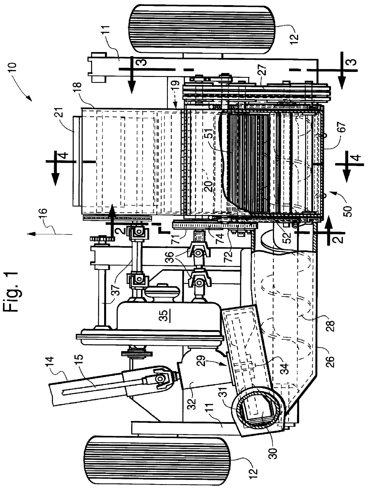
Referring now to the drawings by numerals of reference and first to FIG. 1, 10 denotes a pull-type forage harvester having a frame 11 supported on ground wheels 12. A tongue 14 with a power-take-off drive 15 is adapted to be connected to a tractor which tows harvester 10 in a forward direction indicated by arrow 16.

The harvester has a housing 18 opened forwardly. Mounted on side walls of the housing is a cutterhead 19 having a shaft 20 rotatable on an axes transverse to the direction of travel 16 of the machine. At the front of the harvester there is a header, not shown, which can be a conventional real type pick-up or a row crop which gathers the crop material.

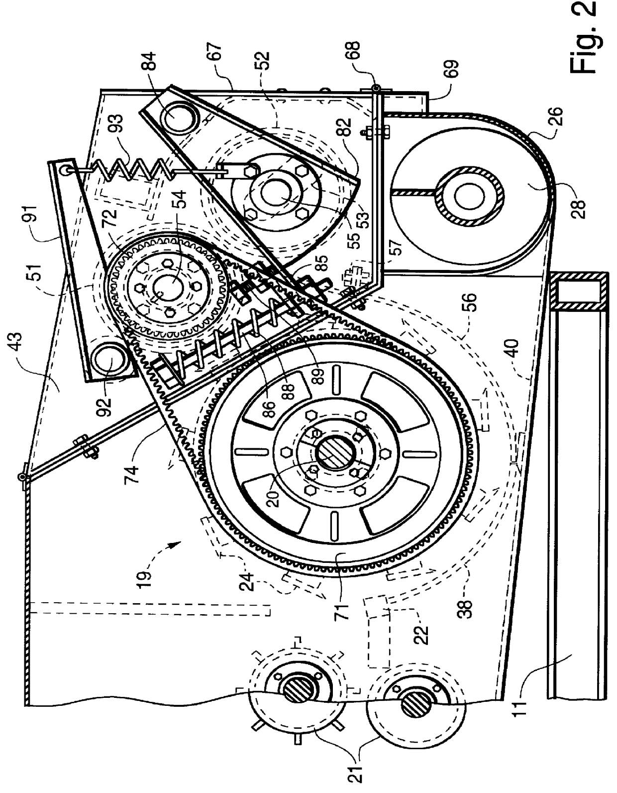
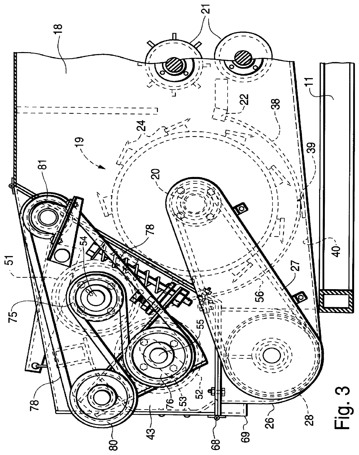
The crop is fed into housing 18 between in-feed rollers 21 (FIG. 4) and over a shear bar 22. The cutterhead has knives 24 mounted around a cylindrical drum 25. The cutting edges of the knives generate a cylinder as the cutterhead rotates. The knives travel for successive cooperation with shear bar 22 to chop the crop material...


PUM


Abstract

In a pull type forage harvester which travels forwardly in a field to pick up crop material and feed it into a housing having a cutterhead with knives rotatable around a transverse axes. The cutterhead chops the crop material and deposits it in a transverse trough having an auger which carries the crop to a lateral discharge location. The improvement comprises a corn processor adapter to which chopped corn is conveyed over a floor to an upper and a lower roll rotatable on axes parallel to the cutterhead. The rolls form a bite to receive the corn and pass it between them to crush the kernels therein. The upper roll is positioned close to the cutterhead knives and in crop stripping relation thereto. The lower roll is positioned over the auger to hold down chopped corn thrown upwardly out of the trough.

Description

The present invention relates to pull-type forage harvesters and more particularly to a corn processor adapter to be build into a pull-type forage harvester whereby the machine can be selectively used to harvest hay crops or corn.BACKGROUND OF INVENTIONA pull-type forage harvester has a wheel supported frame provided with a draw bar or tongue whereby the harvester can be pulled by a tractor in a field having a crop to be gathered. The harvester has a pick-up and infeed whereby the crop is conveyed into a housing. The corn passes over a shear bar into a cutterhead rotatable about an axis transverse to the direction of travel of the harvester. The cutterhead has knives which cooperate with the shear bar to chop the crop fed into the machine.A common pull-type harvester has a trough downwardly and rearwardly of the cutterhead which receives the cut crop. A conveyor in the trough moves the crop to a blower for discharge into a trailing wagon. The trough is parallel to the axes of the cu...

Claims


Application Information

Patent Timeline
Patent Type & Authority Patents(United States)
IPC IPC(8): B02C4/06B02C4/00
CPCB02C4/06
Inventor FISHER, JR., GIDEON A.BEILER, ISRAEL S.
Owner FISHER JR GIDEON A
Why Eureka
Try Eureka