Clamp assembly

a technology of clamping and assembly, which is applied in the direction of washstands, scaffold accessories, lightening support devices, etc., can solve the problems of not being easily and easily installed into the slot structure of the host structure, and the clamping assembly lacks adjustability

Inactive Publication Date: 2000-09-19
CABRIO DESIGN
View PDF7 Cites 89 Cited by
  • Summary
  • Abstract
  • Description
  • Claims
  • Application Information

AI Technical Summary

Benefits of technology

Another significant aspect and feature of the present invention is that once a host structure such as an extruded geometrically configured tube is positioned, such as on a base, vertically or horizontally, the clamp assembly can be engaged and disengaged easily and effectively at any time.
Having thus described embodiments and significant aspects and features of the present invention, it is the principal object of the present invention to provide a clamp assembly which has exceptional versatility and which can be readily and easily installed to a slot in a host structure or other structure at any position therealong.

Problems solved by technology

Clamp assemblies used in prior art display systems or other systems have usually been dedicated to a single purpose, have lacked adjustability, and have not been readily and easily installed into a slot structure on a host structure.
In other words, prior art clamp assemblies for display systems or other systems were intended for a single use, were not easily or readily installed, and allowed little, if any, adjustability.

Method used


Image

  • Clamp assembly
  • Clamp assembly
  • Clamp assembly

Examples


Embodiment Construction

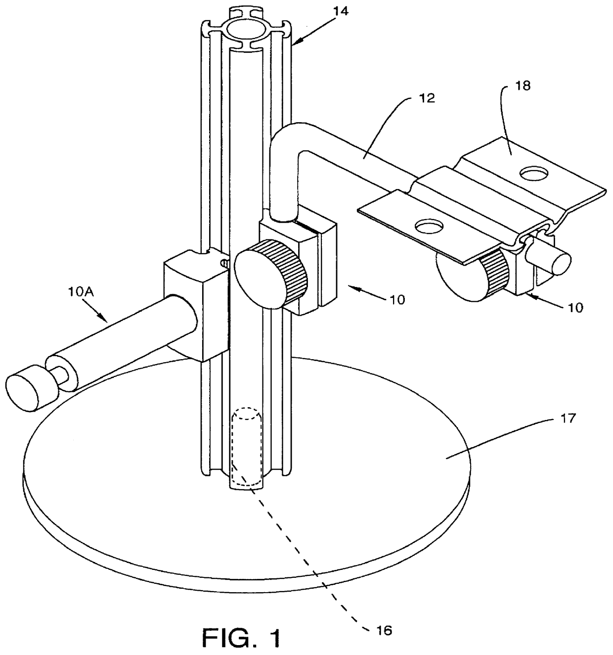
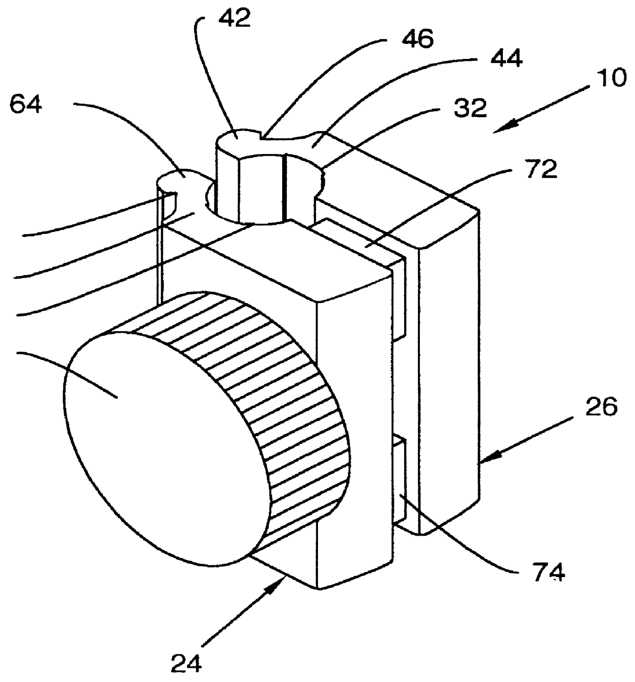
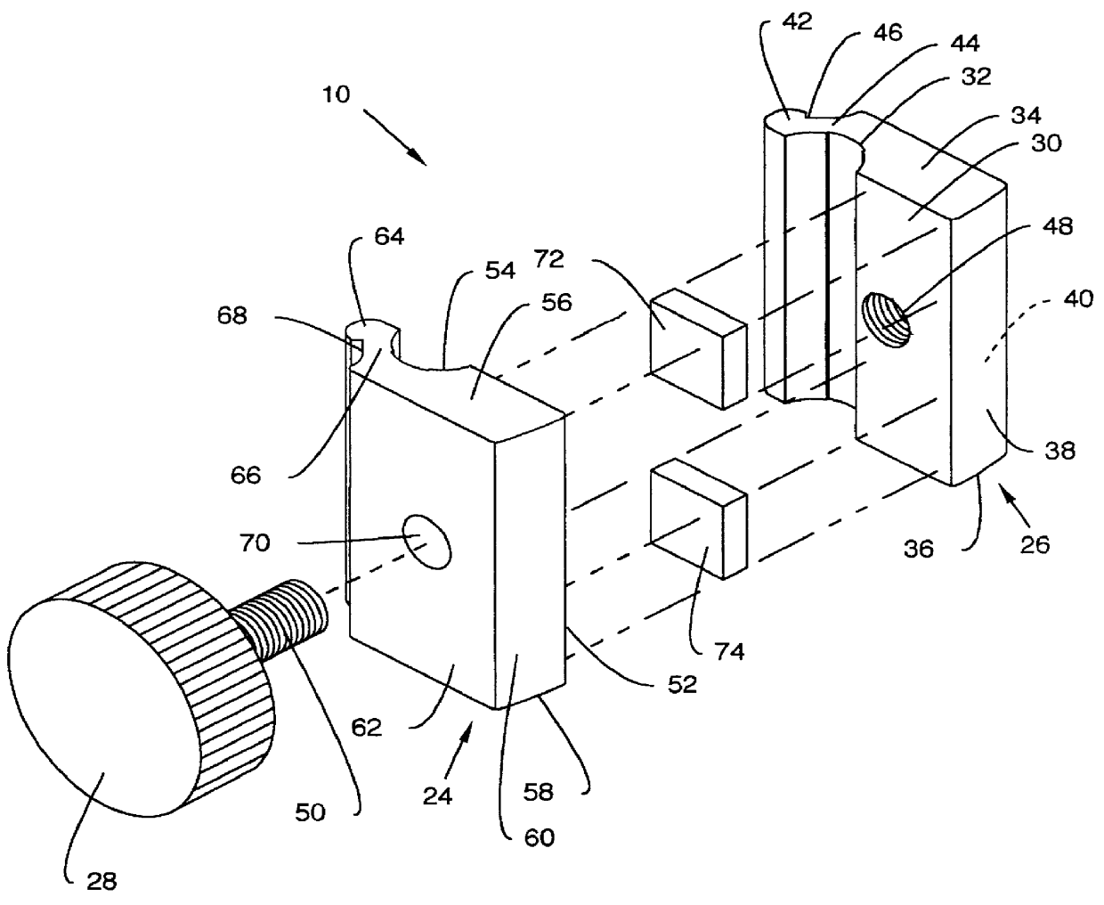
FIG. 5 illustrates a top view of the first step of fastening the clamp assembly 10 and securing a mounting rod 12 to a host structure. The host structure, in this case the extruded geometrically configured tube 14, includes segmented arcuate portions 80a-80n secured to a central cylindrical structure 82 by struts 84a-84n. Slot 86a is formed, in general and for example, between the ends of segmented arcuate portions 80a and 80n, by struts 84a and 84n, and the portion of the cylindrical structure 82 therebetween. In the example, the slots 86a-86n assume an arc-like profile, and any suitably shaped slot can be used against which and into which the teeth 42 and 64 and corresponding grooves 46 and 68 are inserted, engaged and secured. The insertion is initiated by loosely inserting the mounting rod 12 in the arcuate channels 32 and 54 in the jaws 26 and 24 while the actuating knob 28 is rotated to back out the threaded shaft 50 to allow angular flexing of the jaws 26 and 24 with respect ...


PUM


Abstract

A clamp assembly for installation at any position along the length of a slot defined by surfaces of a host structure or other structure. The clamp assembly either can receive a mounting rod for supporting objects or can itself include a mounting rod for supporting objects. In one embodiment the clamp assembly includes a two-piece clamp body composed of a pair of opposing substantially mirror-image jaws each having an inner surface with an arcuate channel and a tooth juxtaposing the arcuate channel. The arcuate channels cooperate to accept and frictionally engage a mounting rod to be affixed to the host structure, and the teeth are for entering into a slot defined by surfaces of the host structure. A tightening member is provided for forcing the jaws together. In an alternate embodiment the clamp assembly includes a one-piece clamp body and a mounting rod. The one-piece clamp body includes engagement tabs for entering into a slot defined by surfaces of the host structure and a threaded hole for receiving a threaded end of the mounting rod, which serves as a tightening member.

Description

CROSS REFERENCES TO CO-PENDING APPLICATIONSNone.1. Field of the InventionThe present invention is for a clamp assembly. More particularly, the present invention pertains to a clamp assembly which has utility especially in conjunction with display systems of the type which include a host structure which supports objects to be displayed, the host structure including surfaces defining a slot and the clamp assembly including structure enabling it to be readily and easily mounted to the slot. The clamp assembly can receive a mounting rod or can itself include a mounting rod; and the mounting rod can support any type of structure, as required.2. Description of the Prior ArtClamp assemblies used in prior art display systems or other systems have usually been dedicated to a single purpose, have lacked adjustability, and have not been readily and easily installed into a slot structure on a host structure. In other words, prior art clamp assemblies for display systems or other systems were in...

Claims


Application Information

Patent Timeline
Patent Type & Authority Patents(United States)
IPC IPC(8): F16M13/02F16M11/20F16M11/24
CPCF16M11/24F16M13/02F16M13/022Y10T24/44974F16M2200/027Y10T24/44504
Inventor PFISTER, JOEL W.
Owner CABRIO DESIGN
Why Eureka
Try Eureka