Brake system for a vehicle and method for operating a brake system for a vehicle

a brake system and vehicle technology, applied in the direction of brake systems, braking components, transportation and packaging, etc., can solve the problems of regenerative braking system that is often not able to exert a generative braking torque on the wheels of the vehicle, and the cost of brake-by-wire systems is relatively high, so as to achieve the effect of easy integration

Active Publication Date: 2013-07-18
ROBERT BOSCH GMBH
View PDF13 Cites 18 Cited by
  • Summary
  • Abstract
  • Description
  • Claims
  • Application Information

AI Technical Summary

Benefits of technology

[0010]By virtue of the brake system being advantageously equipped with the second piston-cylinder unit and by virtue of the first brake booster being advantageously disposed at the second piston-cylinder unit, “decoupling” of the first brake booster from the first piston-cylinder unit is ensured. As will be explained in greater detail hereinafter, that

Problems solved by technology

However, operation of the electric motor, for example the electric drive motor, as a generator normally requires a certain minimum speed of the vehicle.
Therefore, a regenerative braking system is frequently not able to exert a generative brakin

Method used


Image

  • Brake system for a vehicle and method for operating a brake system for a vehicle
  • Brake system for a vehicle and method for operating a brake system for a vehicle
  • Brake system for a vehicle and method for operating a brake system for a vehicle

Examples


first embodiment

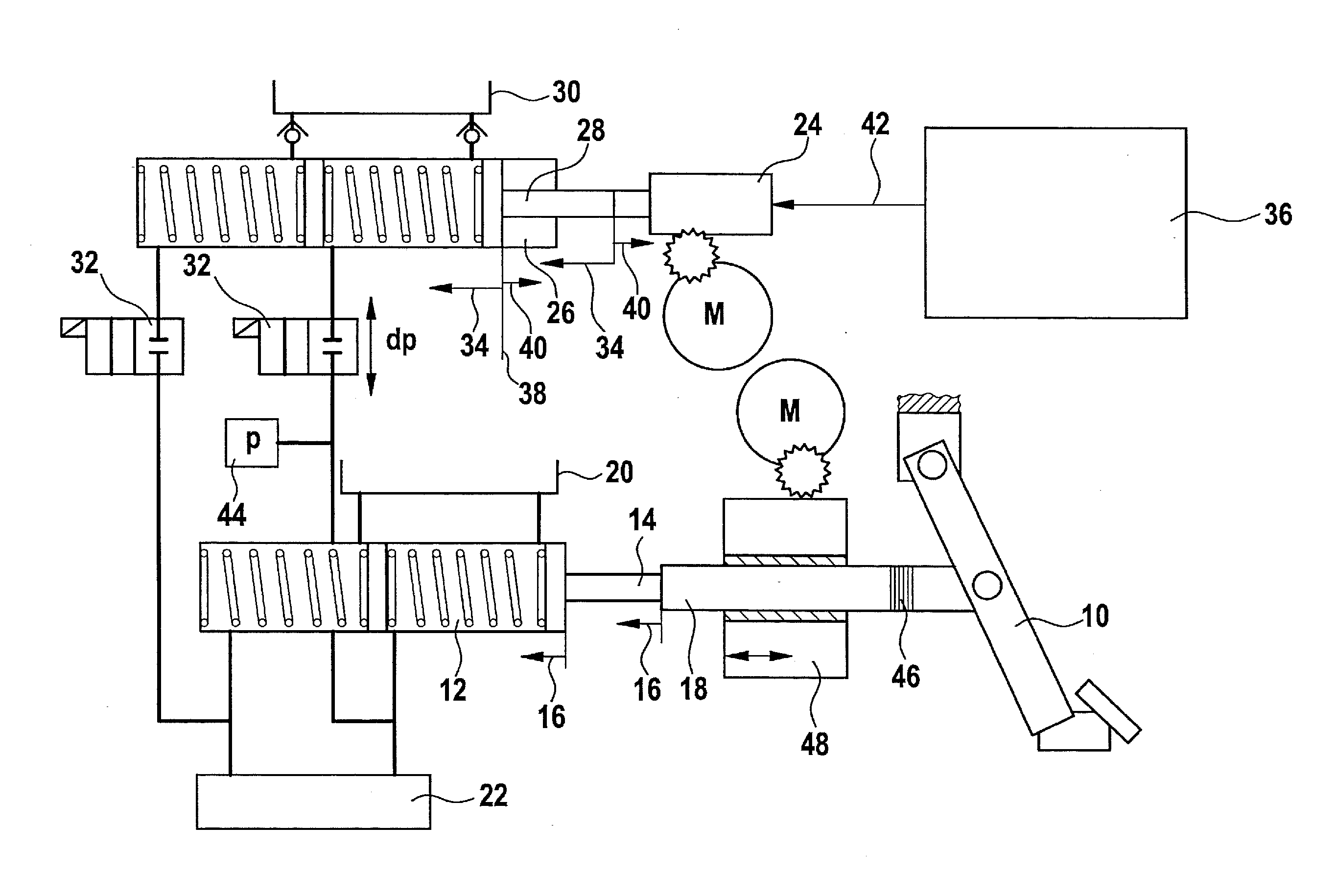
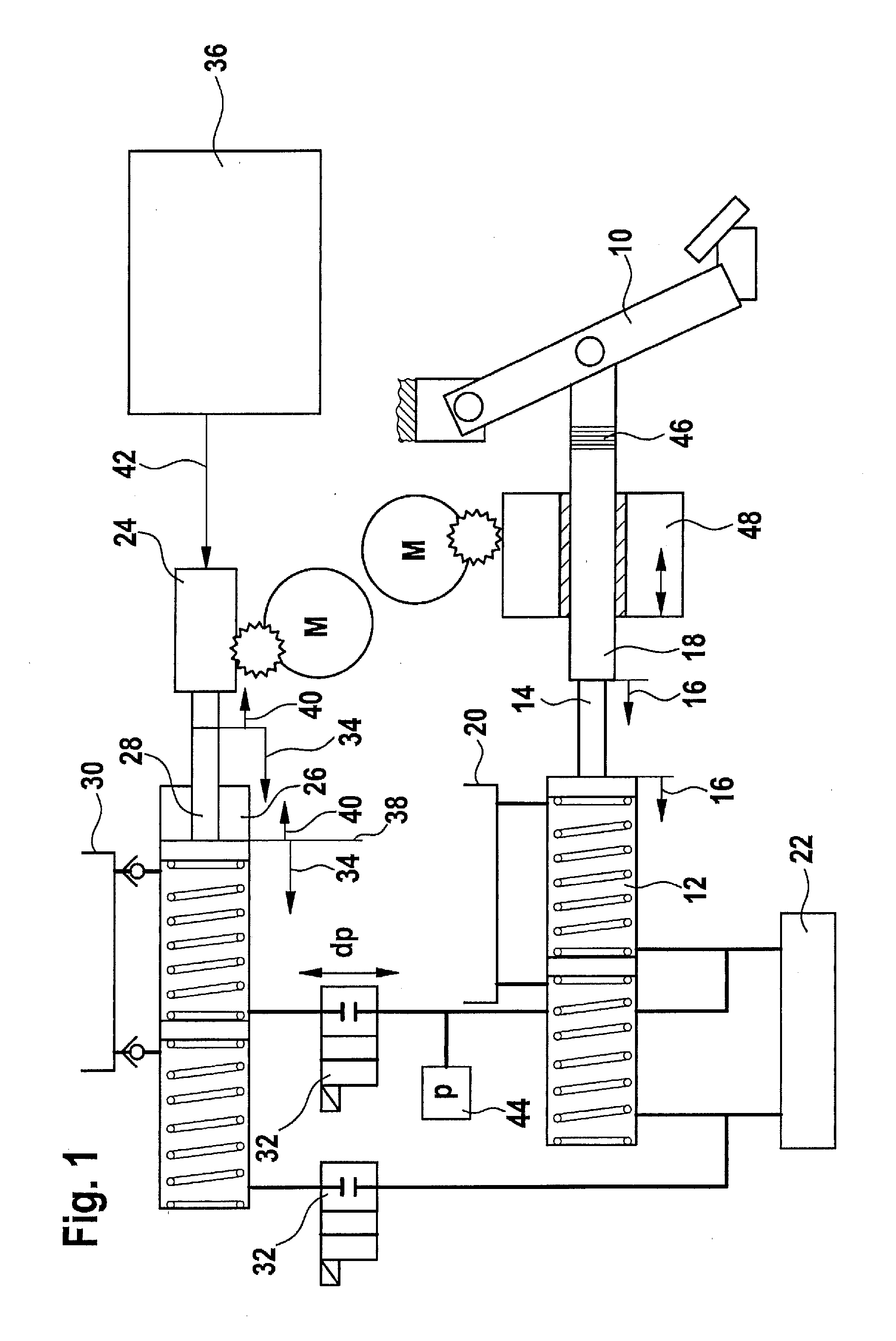
[0023]FIG. 1 shows a schematic illustration of the brake system.

[0024]The brake system illustrated schematically in FIG. 1 has a brake actuating element 10 configured as a brake pedal. The brake system described hereinafter is not, however, limited to a configuration of brake actuating element 10 as a brake pedal. A first piston-cylinder unit 12 is disposed at brake actuating element 10 in such a way that a first piston 14 of first piston-cylinder unit 12 is displaceable by brake actuating element 10 actuated by at least a predefined minimum actuation. Actuation of brake actuating element 10 by at least a predefined minimum actuation may be understood as meaning, for example, displacement of brake actuating element 10 from its (non-actuating) starting position. Further possible forms of the predefined minimum actuation are described below.

[0025]First piston-cylinder unit 12 may, for example, be a master brake cylinder. In particular, first piston-cylinder unit 12 may be a tandem mas...

second embodiment

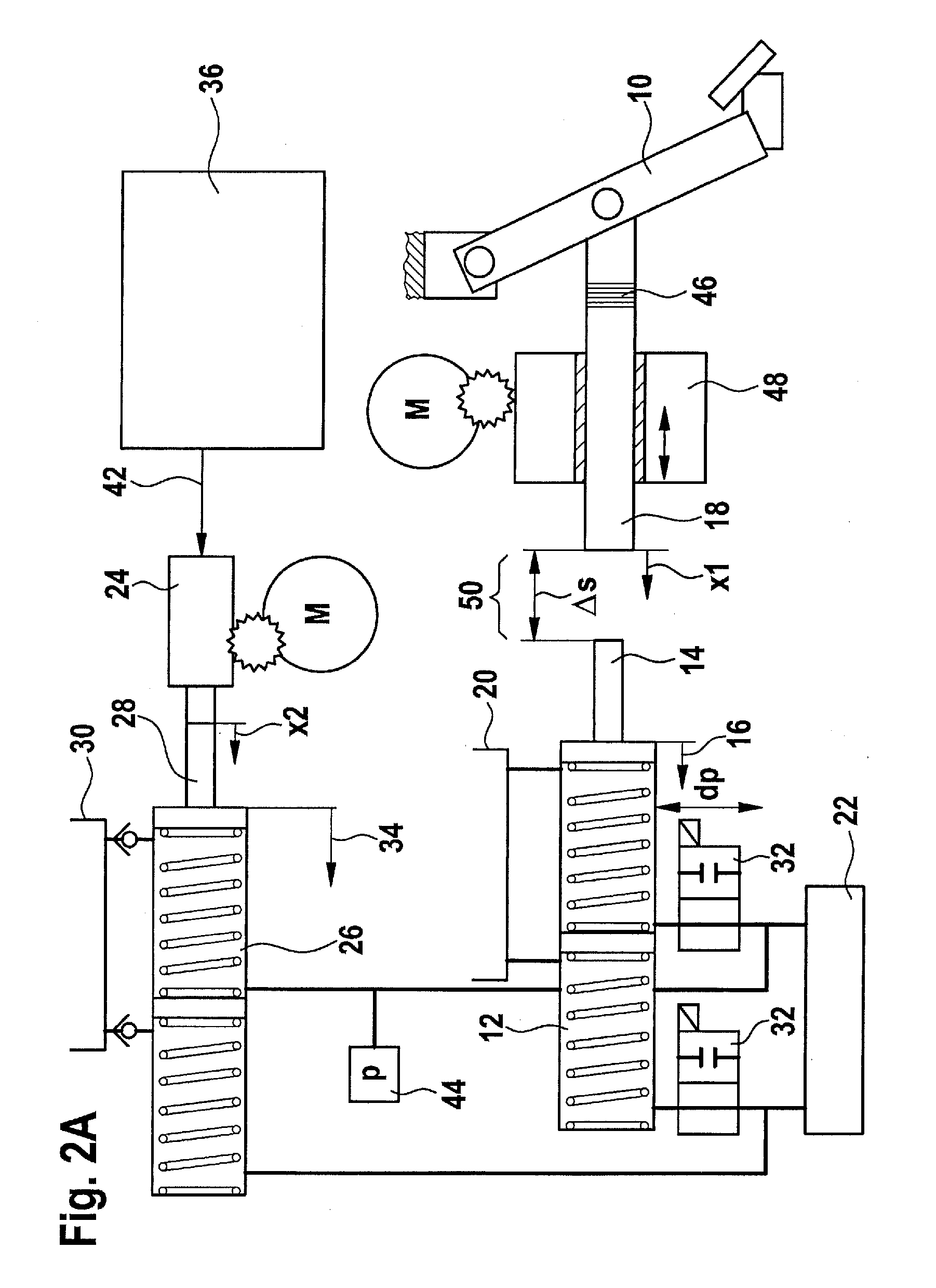
[0052]FIGS. 2A through 2D show a schematic illustration and three coordinate systems to explain the brake system.

[0053]In contrast to the brake system described above, in the case of the embodiment shown here the at least one isolating valve 32 is connected upstream of first piston-cylinder unit 12. The hydraulic coupling of first piston-cylinder unit 12 to second piston-cylinder unit 26 and the at least one brake circuit 22 may therefore be blocked by closing the at least one isolating valve 32. By closing the at least one isolating valve 32 it is possible to prevent a volume of brake medium from flowing out of second piston-cylinder unit 26 into brake medium reservoir 20 via first piston-cylinder unit 12 when first piston 14 is in its (no-force) starting position. Thus, after closing of the at least one isolating valve 32, first brake booster 24 may be used to increase the brake pressure of the at least one wheel brake cylinder despite first piston 14 being in its starting positio...

third embodiment

[0068]FIG. 3 shows a schematic illustration of the brake system.

[0069]In the case of the third embodiment of the brake system shown schematically, brake actuating element 10 is connected to first piston 14 of first piston-cylinder unit 12 by way of a spring device 52. Spring device 52 may, for example, be a spring extending from an end of input rod 18 remote from brake actuating element 10 to an end of first piston 12 toward brake actuating element 10. Instead of an individual spring, however, it is also possible for spring structures having a plurality of springs to be used as spring device 52.

[0070]The spring constant of spring device 52 may be selected in such a way that light actuation of brake actuating element 10 causes slight displacement of first piston 14 into first piston-cylinder unit 12. By that slight displacement of first piston 14 into first piston-cylinder unit 12 it is possible to close the flow openings, configured, for example, as snifter bores, between first pist...


PUM


Abstract

A brake system includes: a brake actuating element; a first piston-cylinder unit having a first piston displaceable by the brake actuating element actuated by at least a predefined minimum actuation such that a first internal pressure in the first piston-cylinder unit is increased; at least one wheel brake cylinder having a brake pressure which is increased using the increased first internal pressure; a first brake booster; and a second piston-cylinder unit having a second piston displaceable by the first brake booster so that a second internal pressure in the second piston-cylinder unit is increased, and to which the at least one wheel brake cylinder is hydraulically connected such that the brake pressure of the at least one wheel brake cylinder is increased by the increased second internal pressure.

Description

BACKGROUND OF THE INVENTION[0001]1. Field of the Invention[0002]The present invention relates to a brake system for a vehicle and a method for operating a brake system for a vehicle.[0003]2. Description of the Related Art[0004]Electric and hybrid vehicles have a brake system configured for regenerative braking, with an electric motor operated as a generator during regenerative braking. The electrical energy obtained during regenerative braking is preferably used, following temporary storage, for accelerating the vehicle. In that manner it is possible to reduce a power loss which is exhibited by a conventional vehicle in the case of frequent braking during a drive, and to reduce energy consumption and pollutant emissions of the electric or hybrid vehicle.[0005]However, operation of the electric motor, for example the electric drive motor, as a generator normally requires a certain minimum speed of the vehicle. Therefore, a regenerative braking system is frequently not able to exert a...

Claims


Application Information

Patent Timeline
IPC IPC(8): B60T13/58B60T13/66B60T7/06
CPCB60T7/042B60T8/4077B60T13/662B60T13/66B60T7/06B60T13/586B60T13/745
Inventor WEIBERLE, REINHARDJAHNZ, TIMO
Owner ROBERT BOSCH GMBH
Why Eureka
Try Eureka