Force monitoring shoe

a technology of force monitoring and shoe, which is applied in the field of force monitoring systems, can solve the problems of not providing an orthopedic shoe, and the true force reading of the weight bearing surface of the user's foot may not be adequately measured by prior devices, and achieve the effect of accurate assessment of the specific weigh

Inactive Publication Date: 2000-09-26
GRAY FRANK B
View PDF3 Cites 175 Cited by
  • Summary
  • Abstract
  • Description
  • Claims
  • Application Information

AI Technical Summary

Benefits of technology

In accordance with the present invention, an improved force monitoring system for use in an orthopedic shoe is disclosed that provides an orthopedic device for monitoring and alerting the wearer of forces subjected to a wearer's foot that exceeds a pre-set range of forces. The apparatus includes a force sensing unit comprising a force sensing beam with at least one strain gage attached thereon, a foot plate covering the beam, the foot plate having an upper surface for contact with the foot of the wearer, and a lower surface connectable to the force sensing beam. The force monitoring system includes a sole portion having an upper surface with at least one cavity therein, the upper surface attachable to the ends of the force sensing beam that is insertable into the cavity, and the sole portion having a lower surface for contact with a supporting surface. A beam control circuitry module including electronic circuitry is mountable within the cavity and is electrically connected to a strain gage attached on the force sensing beam. The electronic circuitry receives signals from the strain gage and converts the strain gage analog signals to digital output signals for remote transmission to a receiver and display unit having a processing means at a remote location. The received output signals are analyzed and compared to pre-selected upper weight limits, or pre-selected lower weight limits. The receiver and display unit displays the numerical weights imposed by the foot of the wearer that lie between the lower and upper weight limits and that exceed the upper weight limits, and displays alarm lights when lower weight limits are not met. No numerical weight value is displayed for weights measured below the pre-selected lower weight limit. The benefits provided by the force monitoring shoe include protection of the affected extremity during the healing process, training of the wearer for rehabilitation, documentation of compliance or non-compliance with a prescribed weight-bearing training program, and accurate assessment of the specific weight applied to an extremity during each step, and / or applied over a multitude of steps.

Problems solved by technology

Prior shoe insert devices do not provide an orthopedic shoe that monitors the differences in weight distribution across a shoe insert foot plate, with resulting measuring of strain created between the rear of a foot plate and the front of the foot plate, with adjustable structures provided within the shoe insert to minimize strain resulting from shoe flex and lateral forces generated by the user's foot.
Therefore true force readings for the weight bearing surfaces of the user's foot may not be adequately measured by prior devices.

Method used


Image

  • Force monitoring shoe
  • Force monitoring shoe
  • Force monitoring shoe

Examples


Embodiment Construction

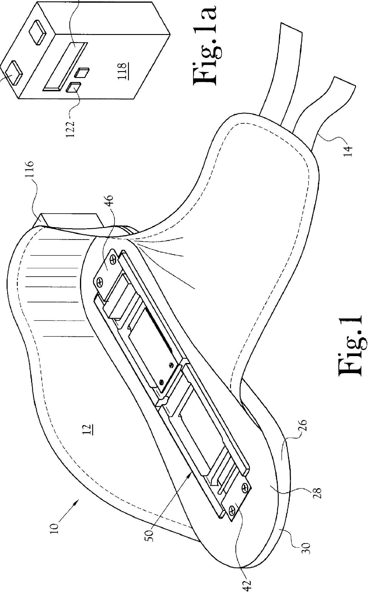
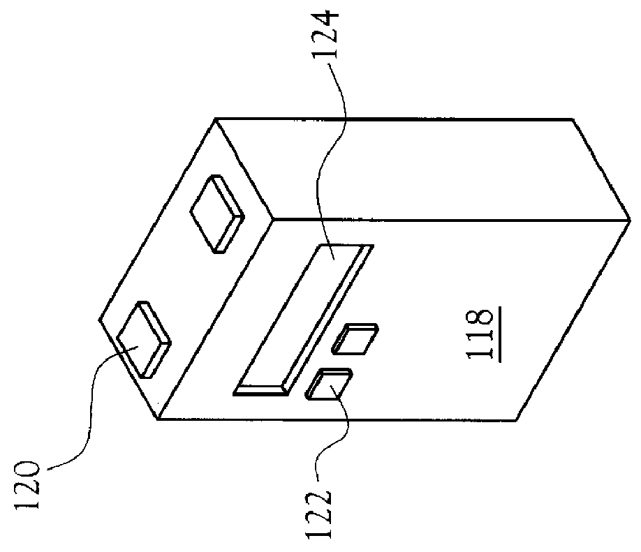
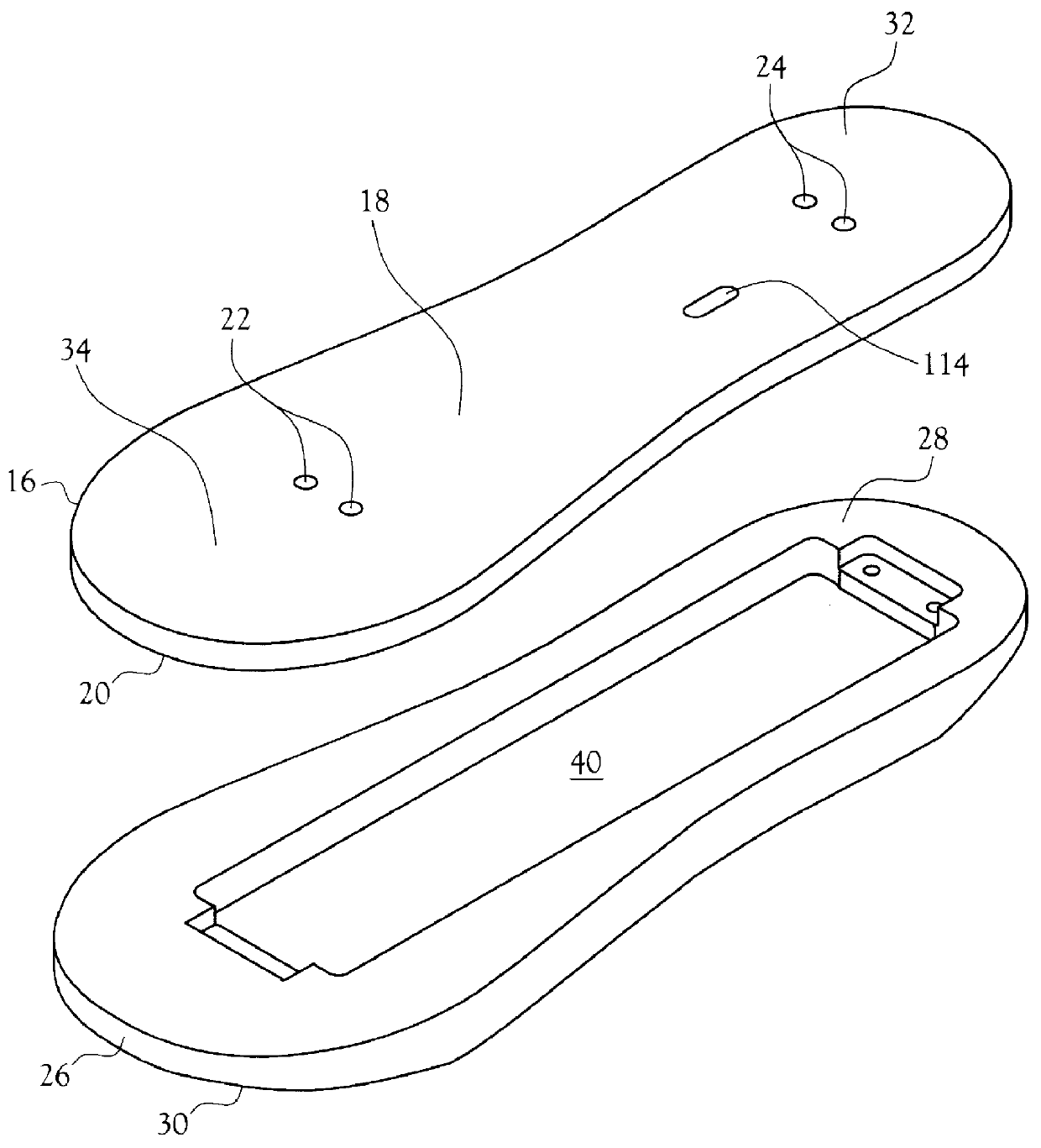
An improved force monitoring system incorporating a force monitoring apparatus within an orthopedic shoe including various features of the present invention is illustrated generally as a force monitoring shoe 10 in the FIGS. 1-12. The force monitoring shoe 10 is designed to provide an orthopedic shoe (see FIG. 1), for measuring force applied to a foot of a wearer, the device providing an indication to the wearer when the force is below or exceeds pre-selected limits, as determined by the wearer or a medical therapist working with the wearer during rehabilitation of an injured lower extremity. A typical wearer of the force monitoring apparatus can be people who have undergone soft tissue or skeletal trauma to a lower extremity, or any other surgical procedure such as hip repair or replacement, knee repair, or ankle repair. The force monitoring apparatus provides instantaneous force readings to a wearer to allow the wearer to reduce the weight on the foot, therefore lessening the forc...


PUM


Abstract

An apparatus and method of operation for measuring forces applied to a wearer's foot, the apparatus providing an indication to the wearer when forces on the foot exceed pre-selected upper limits or do not meet pre-selected lower limits. A body member is disclosed for attachment around the wearer's foot, the body member having an exterior sole and an interior sole portion covered by a rigid foot plate. The foot plate includes an upper support surface for contact with the foot. The interior sole portion includes at least one cavity within, with a force sensing unit attachable partially within the cavity. At least one strain gage is positioned at a midpoint on the force sensing unit, and the force sensing unit is connectable to the underside of the foot plate. An electronic means is mounted within the cavity and is electrically connected to the at least one strain gage. The electronic means receives electronic signals from the strain gage, the signals in proportion to force applied onto the force sensing unit when the wearer's foot applies weight onto the foot plate, with conversion of the signals to output signals for transmission to a signal processing means in a remotely located receiver and display unit. The display unit compares the output signals to upper limits and lower limits, and displays alarms when output signals do not reach lower limits, or exceed upper limits, therefore assisting with therapeutic rehabilitation of an injured lower extremity.

Description

Not Applicable.Not Applicable.BACKGROUND OF INVENTION1. Field of InventionThe present invention relates generally to the field of force monitoring systems and more particularly to a force monitoring system for use in an orthopedic shoe capable of limb load monitoring of forces placed onto a force sensing shoe insert.2. Description of the Related ArtIn the field of force monitoring for orthopedic use, shoe insert devices are available that monitor weight applied onto a limb, with computer analysis available for analyzing weight measurements and triggering alarms depending on the weight and load boundaries programmed into the computer software.In U.S. Pat. No. 5,269,081, to Gray, a force monitoring shoe is disclosed for monitoring the force applied to a patient's leg, as monitored by a force absorption scheme including a heel platform, and a vibration generator located underneath the middle portion of the user's foot, a force monitoring device, and a signaling system. The force monito...

Claims


Application Information

Patent Timeline
Patent Type & Authority Patents(United States)
IPC IPC(8): A61B5/11A43D1/02A61B5/103
CPCA43B3/0005A43D1/025A61B5/1036A43B3/34
Inventor GRAY, FRANK B.PARRIS, JOHN L.GRAY, DAVID H.RIFFERT, RAIMER G.
Owner GRAY FRANK B
Why Eureka
Try Eureka