Percussive down-the-hole hammer and a drill bit therefor

Inactive Publication Date: 2000-10-03
SANDVIK INTELLECTUAL PROPERTY AB
View PDF3 Cites 27 Cited by
  • Summary
  • Abstract
  • Description
  • Claims
  • Application Information

AI Technical Summary

Benefits of technology

An object of the present invention is to provide a drill bit for a down

Problems solved by technology

In addition, often energy transfer from the piston to the drill bit is

Method used


Image

  • Percussive down-the-hole hammer and a drill bit therefor
  • Percussive down-the-hole hammer and a drill bit therefor
  • Percussive down-the-hole hammer and a drill bit therefor

Examples


Example

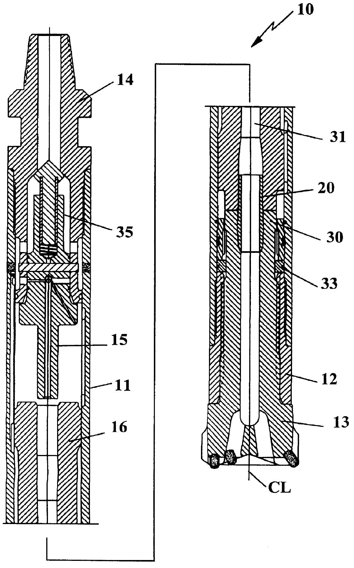
In FIG. 1 there is shown a preferred embodiment of a down-the-hole hammer 10 according to the present invention. The hammer 10 comprises an outer cylindrical casing 11 connectable to a rotatable drill pipe string, not shown, through which compressed air is conducted. A hammer piston 16 reciprocates in the cylindrical casing 11, and compressed air is directed alternately to the upper (rear) and lower (front) ends of the piston to effect its reciprocation in the casing, each downward stroke inflicting an impact blow upon the anvil 30 of a drill bit 13 extending upwardly within the lower portion of the cylindrical casing. The piston comprises a passageway 31 for pressurized air. The percussive down-the-hole hammer further comprises a top sub 14, a check valve 35, a control or fluid feed tube 15, a foot valve 20, a retaining means 33 and a driver sub 12. The down-the-hole hammer 10 is of conventional design except for the shape of the anvil 30 of the drill bit 13. Usually the addition o...


PUM


Abstract

In an air actuated down-the-hole hammer for rock drilling, a piston reciprocates within a casing to impact against a rear anvil surface of a drill bit. A foot valve extends axially between the piston and the drill bit. The anvil surface is inclined downwardly in a radially outward direction to cause liquid on the anvil surface to be discharged in a direction away from the foot valve, to prevent damage to the foot valve which could occur if piston impacts were able to create high-speed liquid streams contacting the foot valve.

Description

The present invention relates to a percussive down-the-hole hammer and a drill bit therefor.PRIOR ARTDuring drilling with down-the-hole hammers under ground, such as in tunnels, the dust generated by the drilling operation often is bound together by the use of water mixed into the pressurized air driving the hammer and flushing the dust away. The down-the-hole hammer is provided with a plastic foot valve located in a central passageway in a drill bit anvil and projecting from the impact surface of the anvil. The foot valve is repeatedly enclosed by a central bore of the reciprocating piston to transfer spent pressurized driving air through the drill bit. When drilling downwardly, water is deposited on the impact surface between successive impacts such that each impact will create a jet stream of water away from the impact surface. The part of the jet stream traveling radially inwardly, however, will cut into the plastic foot valve and finally the valve will break such that the hamme...

Claims


Application Information

Patent Timeline
IPC IPC(8): E21B17/07E21B21/14E21B21/10E21B17/02E21B21/00E21B4/14E21B4/00E21B10/38E21B10/36
CPCE21B4/14E21B10/38E21B21/14E21B21/10E21B17/076
Inventor BECCU, RAINERSBERG, BENGT
Owner SANDVIK INTELLECTUAL PROPERTY AB
Why Eureka
Try Eureka