Device and method to measure inhalation and exhalation air flows

a technology of inhalation and exhalation air flow, which is applied in the field of spirometers, can solve the problems of difficult or uncomfortable use, inability to realistically design spirometers for the range of applications, and inability to accurately measure the flow of human-generated air

Inactive Publication Date: 2000-10-03
EDWARDS RAYMOND A +1
View PDF5 Cites 74 Cited by
  • Summary
  • Abstract
  • Description
  • Claims
  • Application Information

AI Technical Summary

Benefits of technology

It is therefor an object of the invention to provide a spirometer which is simple, handheld, powered by battery, plus power or solar power, which is inexpensive, and which meets the required physical specifications of the American Thoracic Society for accuracy, pressure drop, and range (i.e. total volume measurement).
In the preferred embodiment, the modularity of the upper and lower filtration sections allows biostatic filters to be removed and exchanged without hand contact by the user or a technician. The mouthpiece section and a gross matter filter sack associated therewith are similarly modularly removable and exchangeable. The rotor itself is constructed to be more sensitive to inhalation than exhalation since exhalation is typically stronger, and is protected against accidental lubrication by moisture from the patient's breath by humidity guards. It also utilizes a bearing calibration means such as a bearing screw for simple rotor recalibration. The detection and electronics section is also separate from the remaining mechanical sections of the device, so that the rotor and other mechanical parts--which can become worn or contaminated--are disposable independently. The spirometer electronics tracks air flow per time over a period of time, so that a wide range of pertinent breathing data may be further deduced. An optional air composition detector is used to obtain data for analyzing the content of exhaled air in comparison to the ambient air, particularly but not limited to carbon dioxide and oxygen. Further options, variations and embodiments are described in more detail below.

Problems solved by technology

However, many spirometers are not realistically designed for the range of applications to which they may be subjected, for example, users with lung infections, or frail users, or users who do not have the capacity to follow verbal directions from a respiratory technician, or use under the direction of a respiratory technician who may not provide proper instruction.
In fact, the results of readings from human-generated air flow can vary as much as twenty percent due to poor inhalation / exhalation maneuvers by the patient, i.e., poor effort and timing of the breath cycle.
Also, the mouthpieces of many spirometers are typically oriented in a manner that makes it more difficult or uncomfortable to properly use and therefor to obtain accurate breathing readings.
Similarly, mouthpieces are typically cumbersome to use and do not conform well to the user's mouth.
Known spirometers also do not typically contain adequate safeguards against users who have lung diseases which might contaminate the spirometer, to protect the respiratory technician and subsequent users.
Also, spirometers typically introduce their own resistance and / or back pressure into the air flow path, which can result in inaccurate readings, particularly for a feeble user.
Air flow turbulence is also a problem, and can result in reading variations on the order of 15% to 20% for identical air flow rates for a given spirometer calibration.
For example, basic hand-held spirometers often cannot be used in a hospital bedside environment for continuous breathing monitoring.
For spirometers used in a hospital setting, the readings taken can sometimes be mismatched with the wrong patient due to personnel errors.
The close proximity of these devices as well as the proliferation of wires, may worry or confuse a patient, thus compromising the patient's inhalation or exhalation maneuvers.
In many instances, air expelled through the spirometer blows away from the spirometer user and towards others, which can infect a technician or other person nearby.
Existing spirometers often do not shut down after use, which result in unnecessary power loss.
Nor do they provide simple means to calibrate the rotating element.
Finally, because of the filters they employ, existing spirometers are frequently very large, heavy and cumbersome.

Method used


Image

  • Device and method to measure inhalation and exhalation air flows
  • Device and method to measure inhalation and exhalation air flows
  • Device and method to measure inhalation and exhalation air flows

Examples


Embodiment Construction

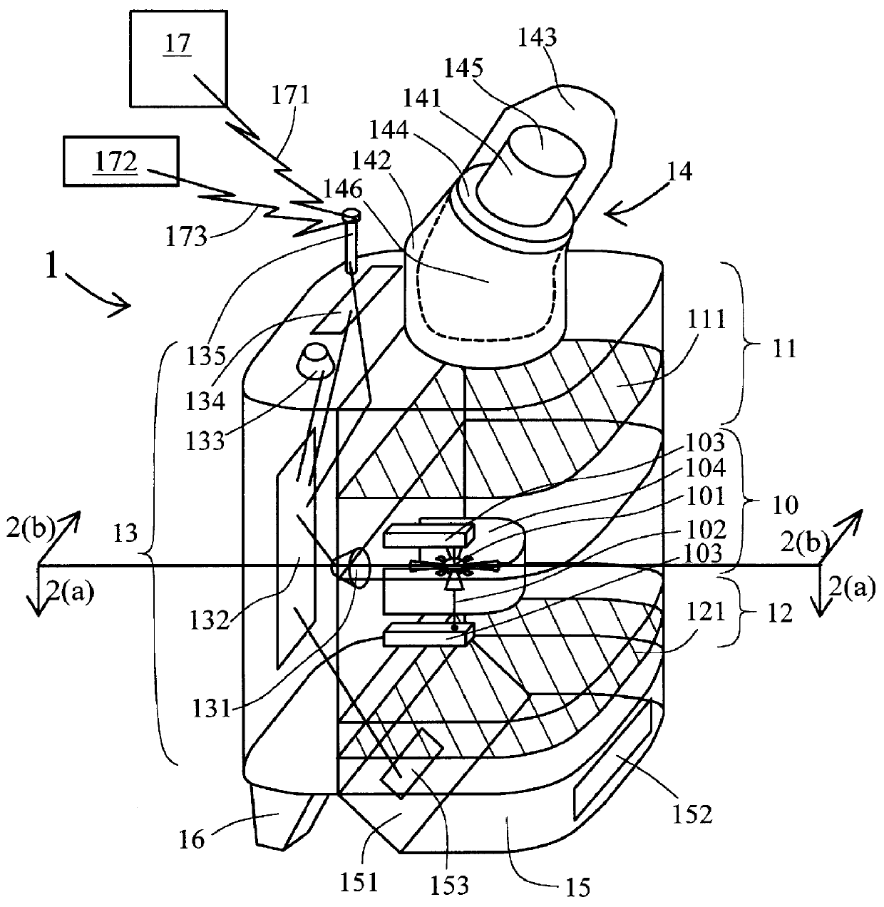
FIG. 1 illustrates the preferred embodiment of the invention in perspective view. Spirometer 1 according to the preferred embodiment comprises four main modular sections, namely, rotor section 10, upper filtration section 11, lower filtration section 12, and detection and electronics section 13. Also illustrated are mouthpiece section 14, air outlet section 15, and electronics section support legs 16 (only one shown, one or more others hidden), which may or may not be distinct modules relative to the four main modular sections to which they are adjacent.

Mouthpiece section 14 further comprises mouthpiece means 141 attached to a tilted, rotatable neck section 142. Mouthpiece 141 should be of an appropriate size to be comfortably placed into the user's mouth for exhalation or inhalation as desired, and different sizes and shapes may be used, for example, for children or people of different mouth sizes. This tilt in neck 142 makes it easier to use spirometer 1 and also to read the digit...


PUM


Abstract

A spirometer is provided which has an air flow path comprising a mouthpiece, filter (such as an air filter or biostatic filter), and an air pathway in which a multiblade transparent windmill rotor rotates when air travels through same. Tips of the rotor are used to detect the rate of rotation providing a train of pulses linearly proportional to the volume of air flowing through the cylindrical air path.

Description

This invention relates to air flow measurement devices, and in particular, to spirometers used to measure inhalation and exhalation.Spirometers are medical instruments which measure inhalation or exhalation flow rates and volumes of the human lung. These typically utilize a rotating device to detect air flows.However, many spirometers are not realistically designed for the range of applications to which they may be subjected, for example, users with lung infections, or frail users, or users who do not have the capacity to follow verbal directions from a respiratory technician, or use under the direction of a respiratory technician who may not provide proper instruction.In fact, the results of readings from human-generated air flow can vary as much as twenty percent due to poor inhalation / exhalation maneuvers by the patient, i.e., poor effort and timing of the breath cycle.Also, the mouthpieces of many spirometers are typically oriented in a manner that makes it more difficult or unc...

Claims


Application Information

Patent Timeline
Patent Type & Authority Patents(United States)
IPC IPC(8): A61B5/09A61B5/08
CPCA61B5/09
Inventor EDWARDS, RAYMOND A.EDWARDS, LUCILE D.
Owner EDWARDS RAYMOND A
Why Eureka
Try Eureka