[0006]The primary object of the present invention is to provide a multi-purpose float switch for auxiliary applications, which can also be adapted for in-line use, that is capable of activating an electrical signal for shutting off an associated fluid producing system when fluid flow in the main discharge line transporting fluid away from the system becomes significantly hindered or clogged and thereby poses a risk of fluid back-up into the system. A further object of this invention is to provide a float switch with a compact housing designed for prompt and cost effective installation in the close-fitting areas sometimes built to accommodate residential air conditioning air handlers, such as but not limited to air conditioning or maintenance closets that typically have a surplus space surrounding the air handler no greater that three or four inches on any one side. It is a further object of the present invention to provide a float switch that is sturdy in construction and designed for responsive and reliable operation. A further object of the present invention to provide a float switch that is capable of being securely installed in a level orientation for proper float switch body movement and will remain substantially in its optimal orientation during its entire period of use. Another object of the present invention is to provide a float switch with a float body having a bottom surface that is located in a position lower than the discharge line to which it is connected so that it will deploy to shut-off the associated fluid producing system when only a very small amount of fluid is collected in the housing surrounding it. It is an object of the present invention to provide a float switch that is protected against air-lock malfunction without the use of vent openings. A further object of this invention is to provide a float switch that is protected against malfunction from debris / mold / rust / algae in condensate / fluid discharge line. In addition, it is a further object of the present invention to provide a float switch that is made from corrosion-resistant materials that resist premature deterioration and malfunction. It is also an object of the present invention to provide a float switch that has cost-effective construction for widespread distribution and use. A further object of this invention is to provide a float switch that positively affects the environment and the conservation of energy resources by promoting air conditioner longevity and the efficient use of higher energy rated systems.
[0007]As described herein, properly manufactured and installed, the present invention would provide a float switch that is prepared for use in an auxiliary or dead end discharge line connected to a fluid producing system, such as but not limited to air conditioning systems, to promptly shut-off that system in response to only a small amount of the fluid being diverted from the system's main discharge line and into the auxiliary line as a result of fluid flow in the main discharge line becoming significantly hindered or clogged, such as with algae, mold, rust, and / or other debris, and failure of any switch device in the main discharge line to shut down the system and avert the fluid back-up damage thereto that would otherwise result if the system were allowed to continue its fluid production. In the alternative, in combination with one or more connecting accessories, the present invention float switch can also be used in an in-line connection with the main discharge line, or a variety of other auxiliary fluid flow applications. The most significant advantages provided by present invention are its design and sturdy construction for reliable performance in shutting off fluid production at the first signs of impaired fluid flow, when only a small amount of fluid (as low as approximately 7.5 mls) has been diverted into its housing. Such a capability will become increasingly important as more energy-efficient air conditioning systems, which generate more condensate than existing systems, are more commonly employed for residential and commercial use. The structure of the present invention housing and extension / arm causes the bottom of the float switch body inside its housing to be positioned lower than the discharge line to which it is connected, resulting in a capability for its float switch body to react to fluid flow impairment situations when only a small amount of fluid is diverted into the housing. No other switch for similar applications is known to have the same structure or capability. The most preferred embodiment of the present invention is small and comprises a housing with a maximum width dimension of approximately three inches, including its connecting extension member or arm. A float switch body is positioned for vertical movement within the housing, and guided in that movement by a concentrically positioned shaft that is secured to the top of the housing. The amount of float switch body displacement needed to active a shut-off signal to stop fluid production is defined by an upper lock-nut and a disk-shaped bottom stop that are both connected to the shaft and are adjusted according to need upon installation, which makes the present invention float switch readily adaptable to a wide variety of applications and changing needs by simple recalibration of the amount of float switch body displacement. The float switch body has a large surface area for enhanced buoyancy and improved responsiveness during operation, with the housing closely positioned around the float switch body and having an open bottom end that is closed by a securely affixed cap or other closure that can be easily removed and replaced during checks for debris / rust / algae / mold in the condensate / fluid discharge line to which it is connected. Preferably, but not limited thereto, the cap or other closure used has a threaded connection and is further secured in its leak-resistant connection with an o-ring. Although the cross-sectional configuration of the present invention housing and float switch body must complement one another to minimize the amount of collected fluid required for float switch activation, the actual configuration of both may be other than circular, and include but not be limited to an ellipse, square, hexagonal, octagonal, pentagonal, non-equilateral polygon, irregular polygon, and the like. A slight bubble or enlargement in the upper portion of the housing allows sufficient fluid / condensate flow to prevent air-lock malfunction without the need for air vent openings in the housing. The extension / arm in the most preferred embodiment of the present invention, which outwardly extends from the housing and is used for connection and fluid communication with a discharge line, also has a widened upper end to assist in preventing air-lock malfunction and further has ratchet-like alignment guides configured to assist an installer in obtaining a level positioning of the housing for proper float switch body operation. Electrical wires extending through the top of the at least partially hollow present invention shaft provide the electrical connection needed with the fluid producing system so that the signal activated by the rise of the float switch body in response to a predetermined amount of fluid collection in its surrounding housing can travel to the fluid producing system and promptly shut it off. The enlarged float switch body and close-fitting housing allow for the collection of a only very small amount of condensate / fluid, such as but not limited to 7.5 ml or 1.5 teaspoons, being required to cause deployment of the float switch body and interruption of condensate production. The present invention is typically made from plastic, and thereby impervious to corrosion, which in combination with its sturdy construction avoids premature deterioration and continued operation for an extended period of time.
[0008]Although the description herein provides preferred embodiments of the present invention, it should not be construed as limiting its scope. For example, variations in the height and diameter of the housing, bottom closure, float switch body, and shaft used; the size and number of threads used on the upper portion of the shaft for housing connection; the length of the extension / arm depending from the housing; the perimeter configuration and dimension of the lock-nut used to tighten the shaft to the housing; the perimeter configuration of the bottom cap or other closure relative to the housing; and the number and spacing of protrusions on the outside surface of the bottom cap or other closure used to facilitate hand manipulation during installation and removal of the closure, if any; in addition to those variations shown and described herein, may be incorporated into the present invention. Thus, the scope of the present invention should be determined by the appended claims and their legal equivalents, rather than being limited to the examples given.
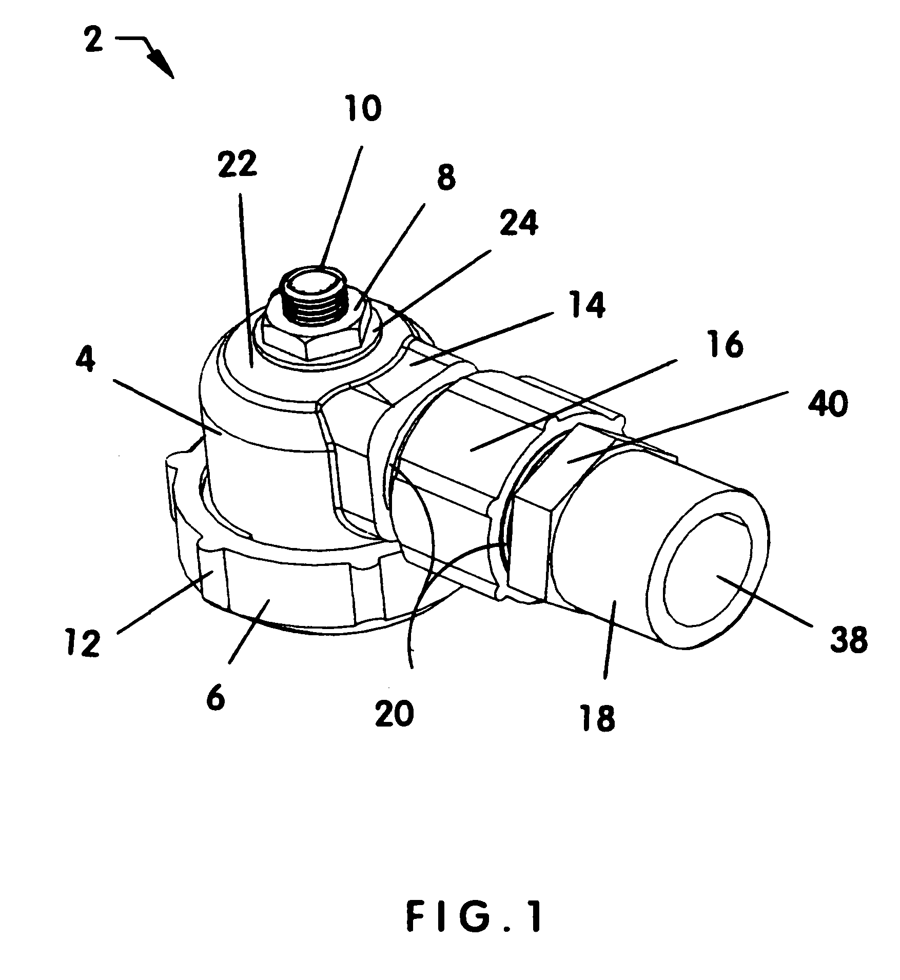
[0009]FIG. 1 is a perspective view of the most preferred embodiment switch assembly of the present invention in an assembled condition and having a housing with an enlarged upper portion, a first type of bottom cap, a vertically-oriented shaft with an upper threaded portion that is secured centrally to the top of the housing by a lock-nut, an extension / arm that is widened at its top end, and a first connecting accessory that is intended for use in installing the most preferred embodiment in auxiliary applications, with the first connecting accessory being shown attached to the housing by a threaded sleeve.
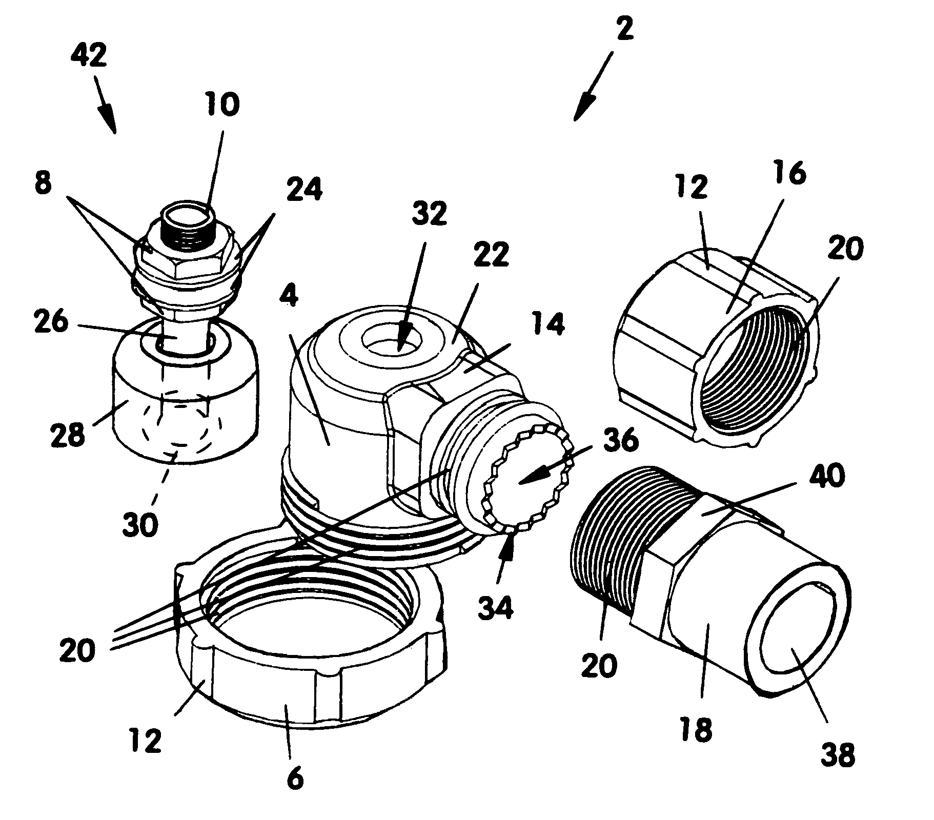
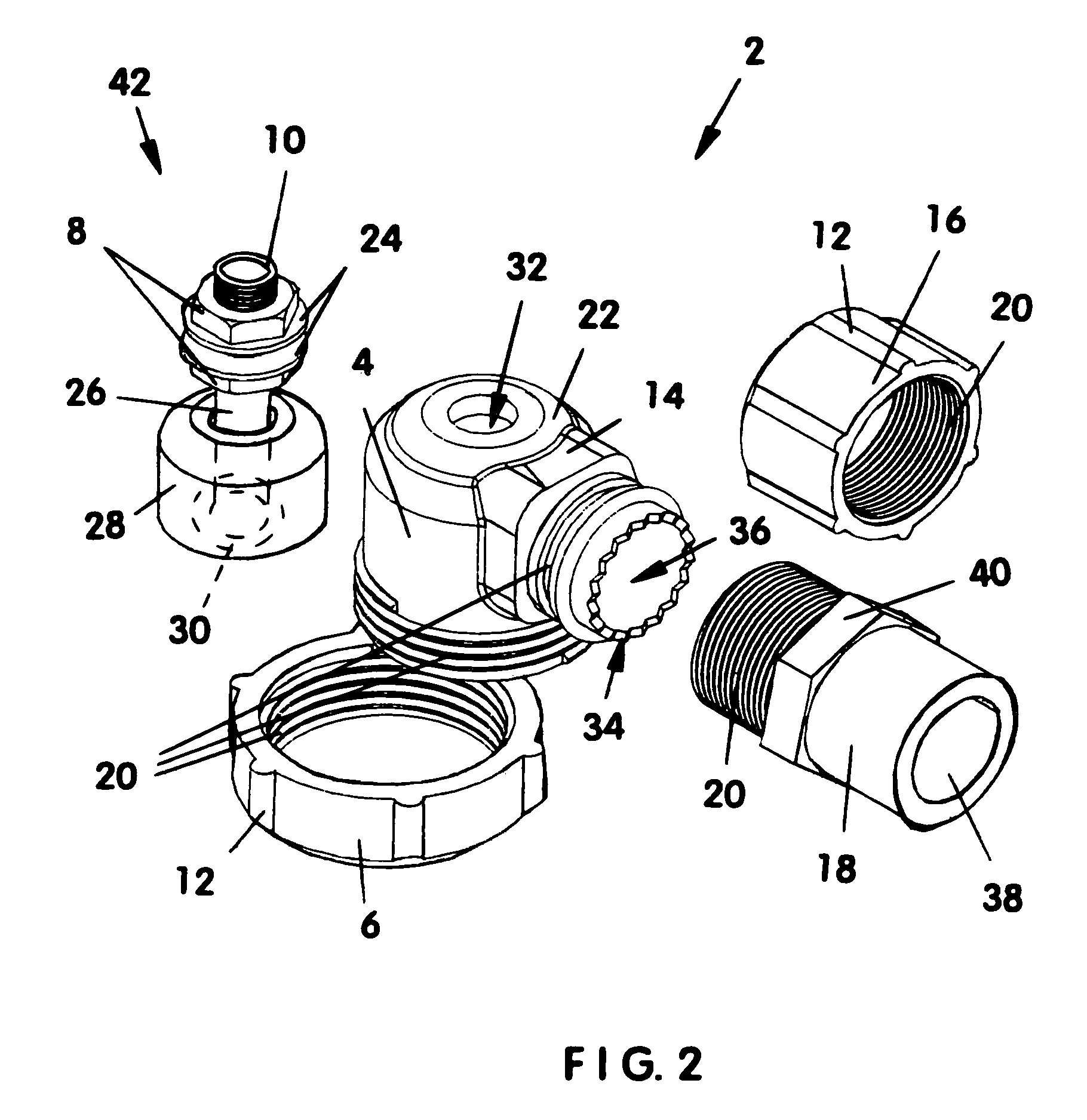
[0010]FIG. 2 is an exploded view of the most preferred embodiment switch assembly of the present invention having a housing with an enlarged upper portion and float leveling means, a threaded bottom cap, a vertically-oriented shaft with an attached float switch body and lock-nuts, the housing also having an extension / arm that is widened at its top end, the first connecting accessory used for attaching the housing to an auxiliary condensate discharge line, and a threaded sleeve used for attaching the distal end of the extension / arm of the housing to the connecting accessory.
[0011]FIG. 3 is a sectioned view of the most preferred embodiment switch assembly of the present invention having a housing with an enlarged upper portion and float leveling means, a threaded bottom cap, a vertically-oriented shaft with an attached float switch body and lock-nuts securing the shaft centrally to the top of the housing, and the connecting accessory used for attaching the housing to an auxiliary condensate discharge line attached to the distal end of the extension / arm of the housing via a threaded sleeve.

