Head position control for a disk drive which performs recording about the rotational center even if the recorded servo information is eccentric

a magnetic disk drive and eccentric recording technology, applied in the direction of data recording, track finding/aligning, instruments, etc., can solve the problem of difficult to increase the density, the head position error of the servo surface is not very small, and the error is not easy to mak

Inactive Publication Date: 2000-10-03
KK TOSHIBA
View PDF7 Cites 61 Cited by
  • Summary
  • Abstract
  • Description
  • Claims
  • Application Information

AI Technical Summary

Problems solved by technology

However, in this dedicated servo system, the head position with respect to the servo surface has a head position error with respect to the written data position.
Because of variations in temperature, vibration of the head movement mechanism, and the like, it is not possible to make this error very small.
Therefore, it was difficult to increase the density by making the track spacing sufficiently narrow.
However, when the disk vibrates, because of the risk of mutual interference between adjacent tracks, it is not possible make the track spacing very narrow, thereby presenting an obstacle to the improvement of recording density.
However, when mounting a disk onto which tracks have been recorded to a rotational hub of a spindle motor, even if the mounting accuracy is improved, it is not possible to avoid some degree of eccentricity, with the center of the track not being in agreement with the center of rotation.
Although it is possible to envision that adjustment can possibly make the eccentricity yet smaller, the required adjustment is extremely delicate, it being extremely difficult to achieve a sufficiently accurate adjustment, so that even if this were possible, the labor required to make the adjustment would present the problem of increased cost.
However, this is accompanied by the problem of a lengthened access time when the head is switched.

Method used


Image

  • Head position control for a disk drive which performs recording about the rotational center even if the recorded servo information is eccentric
  • Head position control for a disk drive which performs recording about the rotational center even if the recorded servo information is eccentric
  • Head position control for a disk drive which performs recording about the rotational center even if the recorded servo information is eccentric

Examples


first embodiment

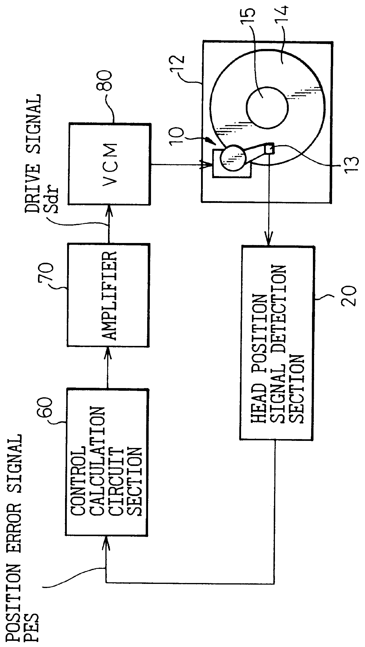
FIG. 7 is a block diagram which shows the configuration of the tracking control section of the

As shown in FIG. 7, the head amplifier 10 amplifies the magnetic data which is stored on the disk and detected by the head 13, and outputs this as a detection signal. The head position detection circuit 20 identifies the servo information which is stored in the servo information recording region from the detection signal, detecting what servo track the current position is, and outputting a head position signal. Additionally, as described with regard to FIG. 2, from the ratio of strengths of the two phase servo bursts, SP and SQ, which are recorded in the servo information recording region, in the case in which the position is between adjacent servo tracks, it is possible to detect at what type of intermediate position this position is. For example, if the interval between the 50th and the 51st tracks is divided into 10 parts and the position is 2 / 10 of the way from the 50th track, a signal ...

second embodiment

FIG. 14 is a control block diagram which shows the configuration of the control section of the present invention.

As is clear in comparison with FIG. 7, in place of the eccentricity data storage section 41, a circular rotational path position table 42 is provided. In the second embodiment as well, there is an eccentricity data measurement section provided for the setting of various sections for the purpose of measuring the eccentricity data, but this is omitted herein.

In the second embodiment, similar to the first embodiment, the eccentricity data measurement section (not shown in the drawing) detects a head position signal with the disk rotating and the head held fixed by a carriage stopper. As already described, when this is done the head position signal can be thought of as a servo signal for the purpose of causing the head 13 to describe a circular rotational path about a center which is the center of rotation. As shown in FIG. 14, a relationship is set up between this and the se...


PUM

PropertyMeasurementUnit
angleaaaaaaaaaa
timeaaaaaaaaaa
frequency bandwidthaaaaaaaaaa

Abstract

Head position control is implemented in a disk drive for the case in which a disk is assembled into the disk drive after a precise track is recorded onto it using an external apparatus, which is capable of high-speed access even if there is eccentricity between a track defined by servo information and the center of rotation of the track. Two phase servo bursts consisting of servo information are recorded onto each of the servo information regions of a disk surface, in mutual alternation, the strength ratio between signals detected from these two phase servo bursts being used to determine to which side the head is displaced. By performing control so that this strength ratio is a prescribed value at each angular position, control is achieved so that the head moves along a circular path of rotation, even if there is eccentricity in the servo circular path defined by the recorded servo information with respect to the center of rotation.

Description

1. Field of the InventionThe present invention relates to a magnetic disk drive and to a head position control method for a magnetic disk drive, and more particularly to a magnetic disk drive and to a head position control method for a magnetic disk drive which are capable of performing high-speed seek and high-accuracy positioning, even if a servo track which is defined by servo information recorded on the surface of the disk is eccentric with respect to the center of rotation.2. Description of Related ArtIn recent years, to achieve an increase in the storage capacity of magnetic disk drives, efforts have been made to achieve even higher density, with an accompanying need to improve access speed. Various methods have been proposed to achieve an increase in magnetic disk drive storage capacity and an improvement in access speed.In a magnetic disk apparatus (hereinafter referred to simply as a disk drive), a magnetic head (hereinafter referred to simply as a head) records data onto a...

Claims


Application Information

Patent Timeline
Patent Type & Authority Patents(United States)
IPC IPC(8): G11B5/596G11B21/10
CPCG11B5/59627
Inventor HASEGAWA, SUSUMUUEMATSU, YUKIHIROYAMADA, TOMOYOSHIUENO, TAKAHISASUZUKI, NOBUYUKIARUGA, KEIJIHASHIMOTO, SHUICHI
Owner KK TOSHIBA
Why Eureka
Try Eureka