Gas detecting method and its detector

Inactive Publication Date: 2000-10-10
FIGARO ENG INC
View PDF8 Cites 18 Cited by
  • Summary
  • Abstract
  • Description
  • Claims
  • Application Information

AI Technical Summary

Problems solved by technology

A problem that the present inventors have worked on the drift of the sensor characteristics.
Projecting coo

Method used


Image

  • Gas detecting method and its detector
  • Gas detecting method and its detector
  • Gas detecting method and its detector

Examples


embodiment

Best embodiment

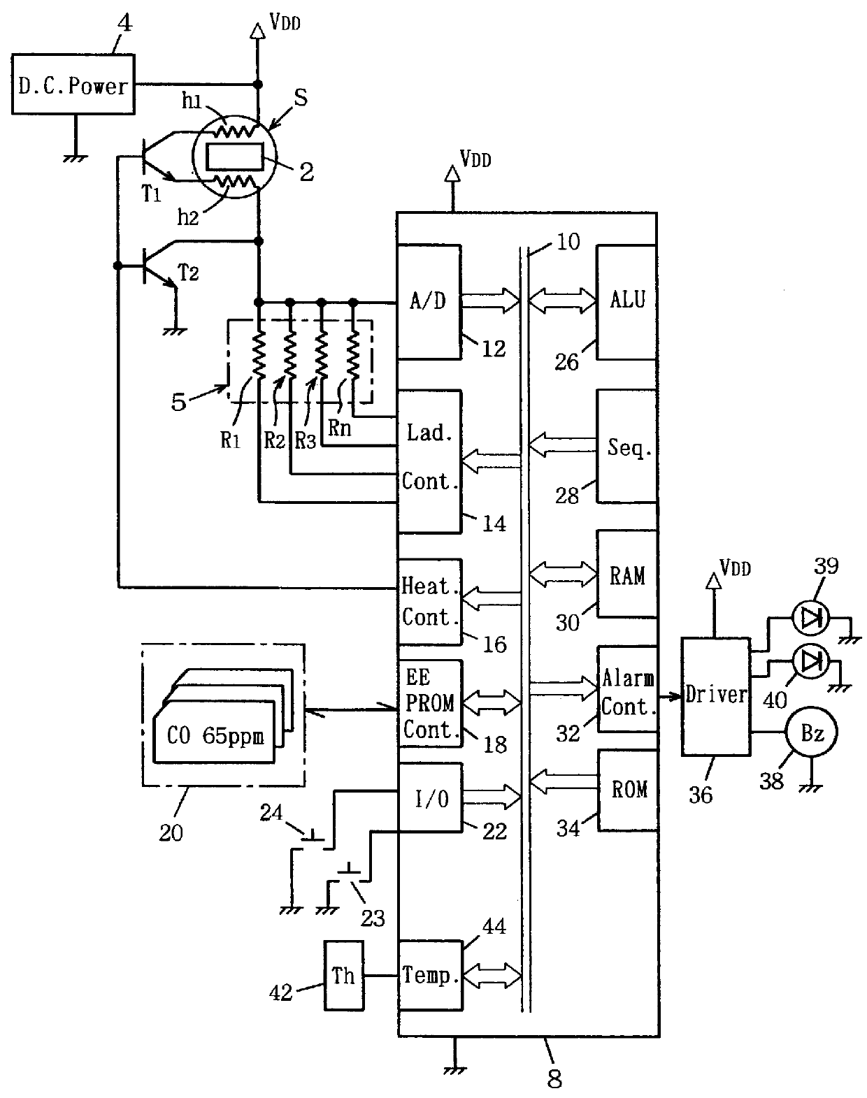
A most preferred embodiment is shown in FIG. 26 and subsequent diagrams. The gas sensor used is TGS203. Data are shown as mean values of 40 to 60 samples of the sensor. When an upper mark and a lower mark are indicated, they represent the maximum and the minimum of the data distribution. As the construction, etc. of the gas detector are common to those of the above-mentioned embodiment, only differences between them will be described.

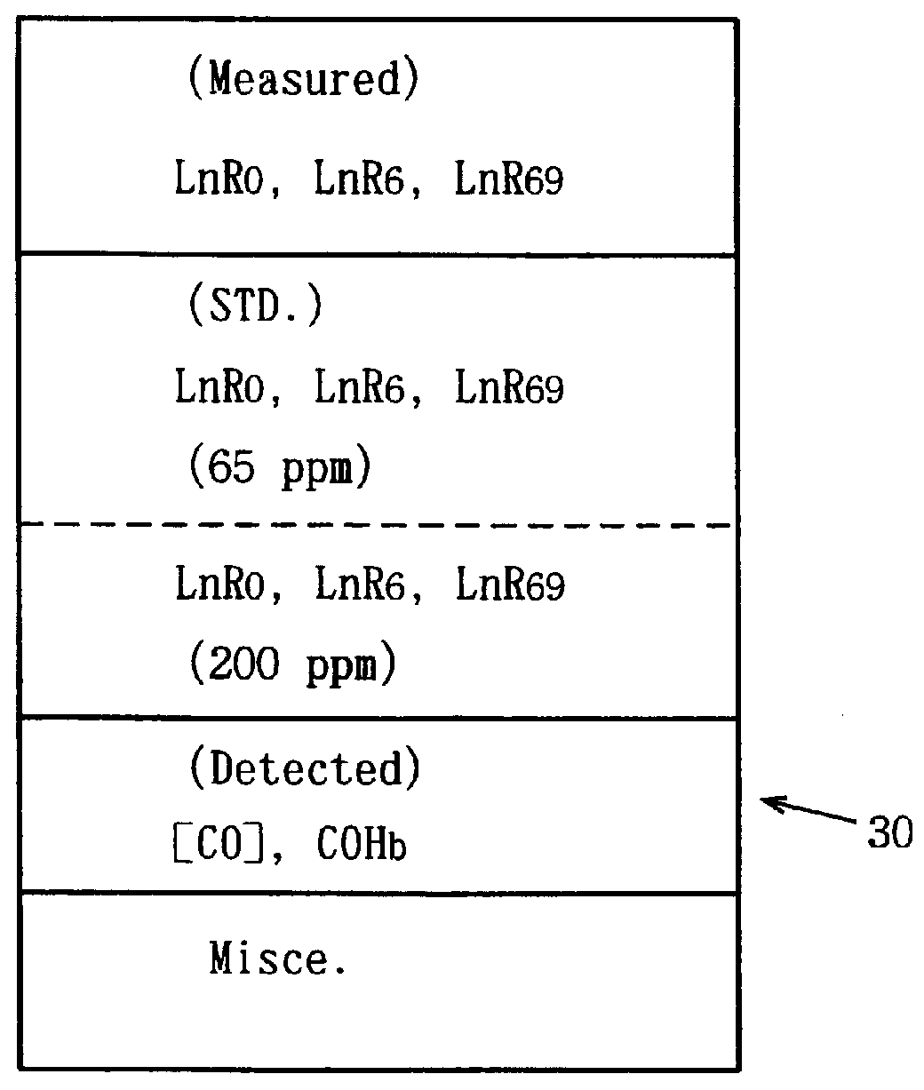
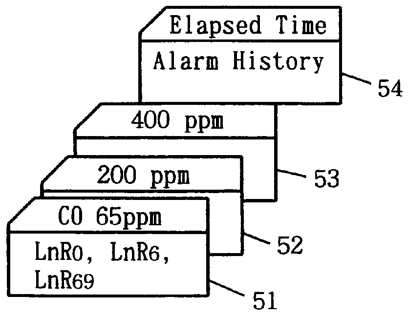
The principle of the most preferred embodiment is shown in FIG. 26. The axis of abscissa is LnR0 (the logarithm of the resistance at the 0th second), and the axis of ordinate is LnR6 (the logarithm of the resistance at the 6th second). When the gas concentration is changed in a constant atmosphere, a gas concentration axis will be obtained in the topological space. A constant atmosphere may be, for example, 20.degree. C. and relative humidity of 40%. The gas concentration range is, for example, from CO 30 ppm to 600 ppm. LnR0 and LnR6 for...


PUM


Abstract

A metal oxide semiconductor is subjected to a temperature change, and signals measured at two timings in the course of the temperature change are used to define a two-dimensional topological space. In the topological space, two axis, an axis indicating the concentration of the gas to be detected and an axis corresponding to drift are defined, and the topological space is represented by an oblique coordinate system. The gas concentration is determined from projection of measured data onto the gas concentration axis.

Description

The present invention relates to detection of a gas with a metal oxide semiconductor gas sensor, and in particular, it relates to a technology of detecting a gas by subjecting a gas sensor to temperature change.PRIOR ARTAn SnO.sub.2 type CO sensor TGS203 (TGS203 is a trade name of Figaro Engineering Inc.) is a metal oxide semiconductor gas sensor that uses temperature change. This gas sensor operates in cycles and every cycle has a period of 150 seconds. The first 60 seconds of the cycle are allotted to a higher temperature period, and the subsequent 90 seconds to a lower temperature period. The final temperature of the higher temperature period is 300.degree. C., and the final temperature of the lower temperature period is 80.degree. C. The concentration of CO is detected from the resistance of the metal oxide semiconductor at the end of the lower temperature period. The resistance of the sensor is substantially in inverse proportion to the CO concentration. The ratio of hydrogen s...

Claims


Application Information

Patent Timeline
IPC IPC(8): G01N27/12G01N33/00
CPCG01N33/004G01N27/122G01N27/12
Inventor SHIOIRI, AKIRAUDAKA, TOSHIHIROSHINNISHI, KAZUYATAKAMATSU, KAZUKO
Owner FIGARO ENG INC
Why Eureka
Try Eureka