Printer device

a printing device and printing technology, applied in the direction of printing, measuring apparatus components, instruments, etc., can solve the problems of inability to represent low concentration, inability to easily represent low concentration, and inability to emit ink

Inactive Publication Date: 2000-10-10
SONY CORP
View PDF3 Cites 4 Cited by
  • Summary
  • Abstract
  • Description
  • Claims
  • Application Information

AI Technical Summary

Problems solved by technology

However, with this method, the ink becomes unable to be emitted if the voltage or the pulse width applied to the piezoelectric device or the heating device is lowered excessively.
Thus, there is a limitation to the minimum liquid drop size such that the number of stages of the gradation that can be represented is only small.
In particular, the low concentration cannot be represented with ease such that the natural image cannot be printed out satisfactorily.
However, if this second method is used for printing with the same dot density as that in the first method, the resolution is one-fourth of that of the first method such that an extremely coarse image is produced.
Thus, this second method is insufficient for printing out the natural image.
However, in the above-described inner mixing type printer device, the quantitation medium tends to be diffused into the emission medium in the emission medium nozzle during the operation stand-by time when the quantitation medium is not mixed with the emission medium.
In addition, the emission medium is likely to flow unnecessarily into the connecting portion during mixing-emission of the quantitation medium and the emission medium, or the quantitation medium is likely to flow unnecessarily into the emission medium.
If such diffusion between the quantitation medium and the emission medium occurs, the dilution liquid as the emission medium is gradually colored, or the quantitation medium, such as the ink, is diluted, thus affecting the concentration of the emitted mixed liquid droplets to render it difficult to obtain the correct gradation in concentration.
In case of unnecessary inflow in the former case, th

Method used


Image

  • Printer device
  • Printer device
  • Printer device

Examples


Embodiment Construction

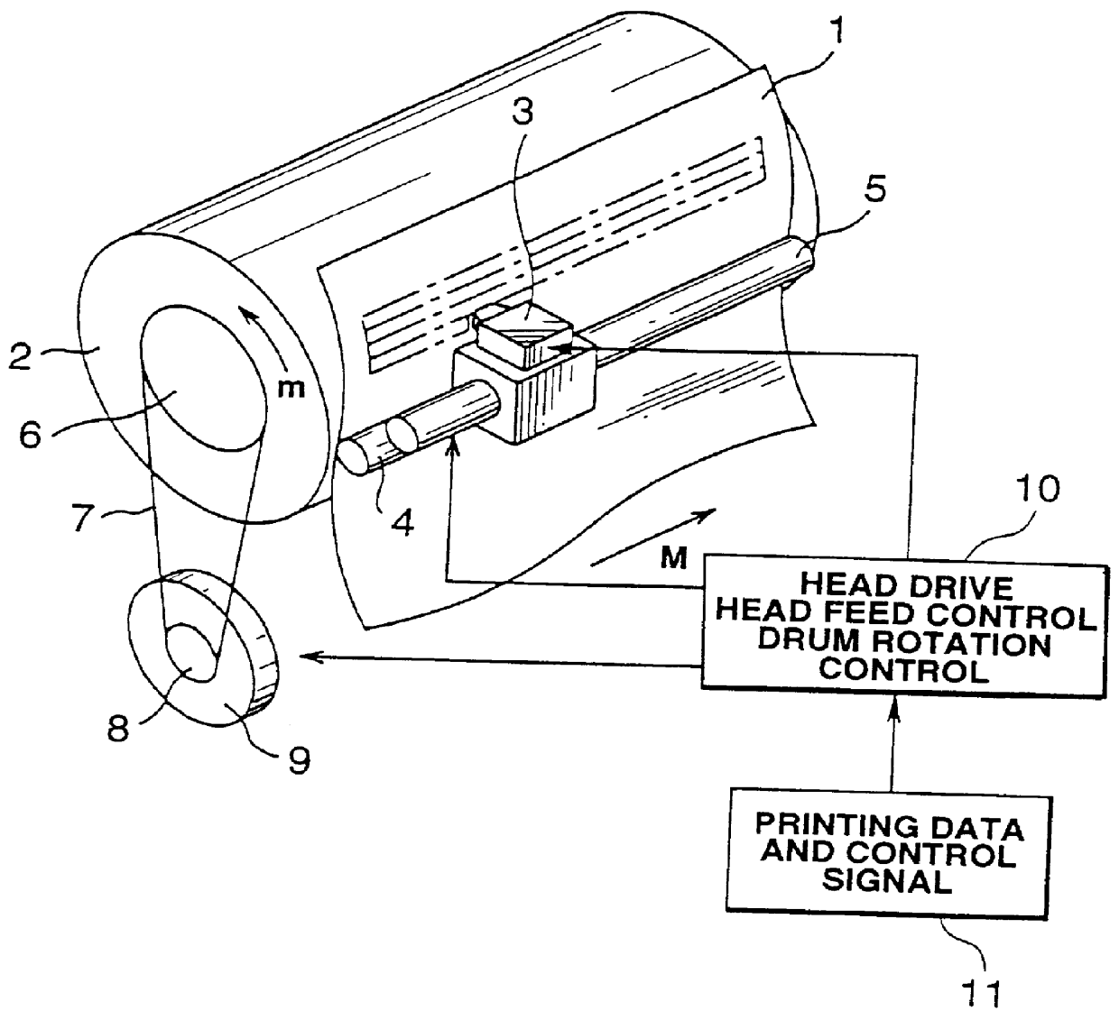
Referring to the drawings, preferred embodiments of the present invention will be explained in detail. The following description is made of a so-called `carrier jet` type printer device in which the ink and the dilution liquid are used as the quantitation medium and the emission medium, respectively.

The printer device according to the present invention is a so-called serial type printer device mainly comprised of a drum 2 supporting a printing paper sheet 1 as a printing support and a printer head 3 used for recording on the printing paper sheet 1.

The printing paper sheet 1 is held by being pressed against the drum 2 by a paper sheet pressing roll 4 mounted parallel to the axis of the drum 2. A feed screw 5 is mounted parallel to the axis of the drum 2 in the vicinity of the outer periphery of the drum 2. The printer head 3 is held by this feed screw 5. That is, the printer head 3 is moved axially of the drum 2, as indicated by arrow M, by rotation of the feed screw 5.

On the other h...


PUM


Abstract

A printer device for realizing correct representation of the gradation. After oozing a quantitation medium 45 from a quantitation medium nozzle 53, the printer device causes an emission medium 49 from an emission medium nozzle 54 for mixing with the quantitation medium 45 for emitting the resulting mixed liquid. During the time which elapses since emission of the quantitation medium 45 from the quantitation medium nozzle 53 until reversion of the liquid surface of the quantitation medium 45 to the opening end of the quantitation medium nozzle 53, the quantitation medium 53 is pressurized in a direction of pulling the liquid surface of the quantitation medium 45 into the quantitation medium nozzle 53. Also, during the time which elapses since the emission of the emission medium 49 from the emission medium nozzle 54 until reversion of the liquid surface of the emission medium 49 to the opening end of the emission medium nozzle 54, the emission medium 49 is pressurized in a direction of pulling the liquid surface of the emission medium 49 into the emission medium nozzle 54.

Description

1. Field of the InventionThis invention relates to a printer device for emitting a printer device for mixing a medium for quantitation and a medium for emission and emitting the resulting mixed mediums. More particularly, it relates to a printer device in which the pressure applied to at least one of the medium for quantitation and the medium for emission for enabling correct gradation representation.2. Description of the Related ArtRecently, computerized document preparation, termed desk publishing, has become popular particularly in an office, such that an increasing demand is raised for outputting not only letters or figures but also colored natural images, such as photos, along with the letters or figures. In keeping up therewith, it is required to have a natural image printed to a high quality such that gradation representation by regeneration of a half tone is becoming crucial. On the other hand, a so-called on-demand type printer device, which emits ink droplets only when req...

Claims


Application Information

Patent Timeline
IPC IPC(8): B41J2/21
CPCB41J2/211
Inventor ANDO, MAKOTO
Owner SONY CORP
Why Eureka
Try Eureka