Method for surveying the condition of a control valve, and a valve apparatus

a technology for control valves and valve apparatuses, applied in the direction of water mains, gas/liquid distribution and storage, electric winding testing, etc., can solve the problems of complex testing on the field, diagnostic systems that do not include any deduction procedures by which faults could be located, etc., to increase process feasibility, reduce costs, and increase process safety

Inactive Publication Date: 2000-10-17
NELES CONTROLS
View PDF20 Cites 84 Cited by
  • Summary
  • Abstract
  • Description
  • Claims
  • Application Information

AI Technical Summary

Benefits of technology

The final advantage to be gained through the on-line diagnostics is the increasing safety of the process and decreasing of the costs while the feasibility of the process will be increas

Problems solved by technology

The testing equipment often also includes complicated sensors that can make the testing on the field complicated (U.S. Pat. N

Method used


Image

  • Method for surveying the condition of a control valve, and a valve apparatus
  • Method for surveying the condition of a control valve, and a valve apparatus
  • Method for surveying the condition of a control valve, and a valve apparatus

Examples


Embodiment Construction

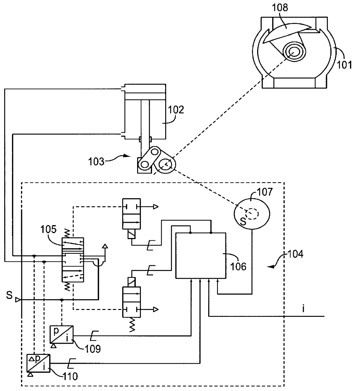
FIG. 1 illustrates an apparatus comprising a control valve 101, an actuator 103 driven by a cylinder-piston device 102 and a positioner 104. The actuator is controlled by a pilot valve 105. Messages of the positioner are processed by a printed circuit card 106 where the control information is stored in. A sensor 107 measures the position s of a closing member 108, a sensor 109 measures the input pressure p.sub.s of the positioner and a sensor 110 measures the difference .DELTA.p between the input and output pressure of the actuator. These sensors are located in the positioner. The flow of the different electric messages and measurements is marked on the diagram. Control signal i is input in the system.

Alert 1 indicates a circuit card problem of the positioner, as stated above, but it is not a part of the present invention.

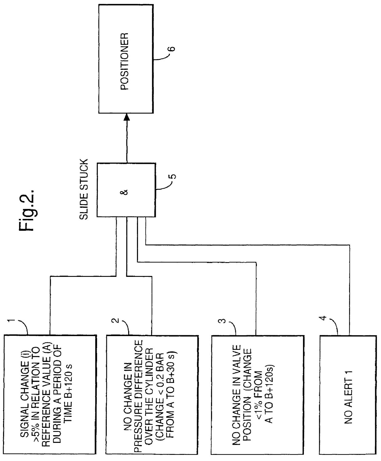
Alert 2 indicates a slide problem of the control valve.

FIG. 2 illustrates as a diagram four different conditions by means of which the deduction concerning the ale...


PUM


Abstract

PCT No. PCT/FI97/00359 Sec. 371 Date Dec. 4, 1999 Sec. 102(e) Date Dec. 4, 1999 PCT Filed Jun. 9, 1997 PCT Pub. No. WO97/48026 PCT Pub. Date Dec. 18, 1997A method and a valve apparatus for surveying the condition of a control valve. The position of the valve (101) is adjusted by means of an actuator (103) controlled by an electropneumatic positioner (104) and operated by means of pressure medium. The operation of the valve is monitored by sensors (109, 110, 107) that read the readings from the control signal, the input pressure of the positioner, the difference between the input and output pressure of the actuator, and the position of the valve. A fault causing a deviating reading will be located by using the readings given by the sensors and deduction rules stored in the microprocessor of the actuator. In an initial situation, when the valve is in balance state, the readings given by the sensors are stored at least from the control signal, valve position and the difference between the input and output pressure of the actuator. When the operation is continued, the readings given by the sensors are compared with the readings of the initial situation. If the deviations exceed certain limit values and remain there continuously for a certain period of time, a fault message will be given that indicates the location of the fault.

Description

The present invention concerns a method for surveying the condition of a control valve apparatus, the position of which is adjusted by means of an actuator controlled by an electropneumatic positioner and operated by means of pressure medium, whereby the operation of the valve is monitored by sensors that during the valve operation read at certain reading intervals the readings at least from the control signal of the valve, the input pressure of the positioner, the difference between the input and output pressure of the actuator, and the position of the valve, and the fault causing the deviating reading is located by means of a microprocessor by using the readings given by the sensors and deduction rules stored in the microprocessor.The invention also concerns a control valve apparatus comprising a valve, an actuator driven by means of a cylinder-piston device, and an electropneumatic positioner, sensors for monitoring at least the control signal of the valve, the input pressure of ...

Claims


Application Information

Patent Timeline
IPC IPC(8): F16K37/00G05B9/02
CPCF16K37/0083F16K37/0091G01R31/06F15B19/005F15B2211/6309F15B2211/6313F15B2211/6336F15B2211/7053F15B2211/857F16K31/1635G01R31/72Y10T137/8175Y10T137/8242
Inventor METSO, MIKAPYOTSIA, JOUNI
Owner NELES CONTROLS
Why Eureka
Try Eureka