Closure device for laboratory receptacles

a technology for closing devices and receptacles, which is applied in the direction of closures using stoppers, laboratory glassware, liquid handling, etc., can solve the problems of lack of sealing capacity, difficult to apply and remove, and easy to be damaged

Inactive Publication Date: 2000-10-24
MATRIX TECH
View PDF28 Cites 96 Cited by
  • Summary
  • Abstract
  • Description
  • Claims
  • Application Information

AI Technical Summary

Problems solved by technology

Some are relatively easy to apply and remove, but lack adequate sealing capability.
Others provide a satisfactory seal but are extremely difficult to apply and remove, sometimes resulting in splashing and cross contamination of specimens contained in the receptacles.
Additional drawbacks of conventional closure devices include an inability to function satisfactorily at elevated or reduced temperatures, and seal failures at differential pressures on the order of 0.5 atmospheres and below.

Method used


Image

  • Closure device for laboratory receptacles
  • Closure device for laboratory receptacles
  • Closure device for laboratory receptacles

Examples


Embodiment Construction

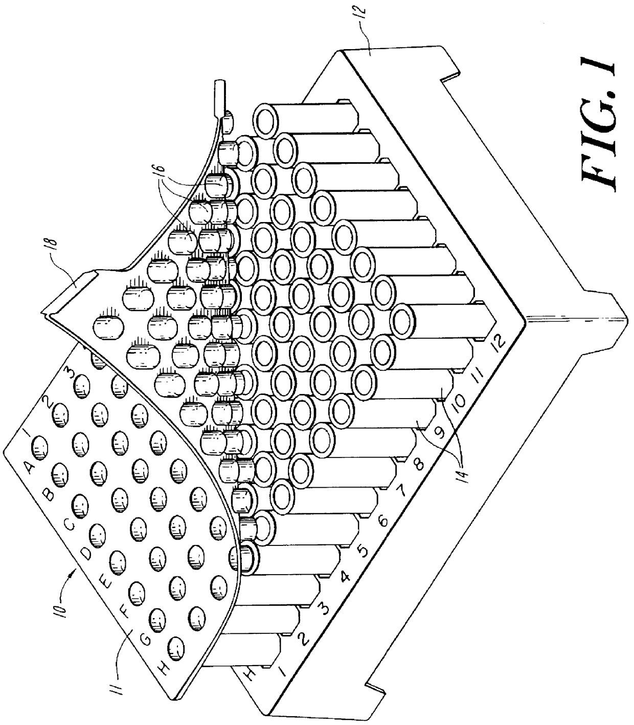
Referring initially to FIG. 1, a closure device in the form of a cap mat 10 is shown partially removed from a rack 12 of test tubes 14. The cap mat 10 includes a flexible cover 11 configured and dimensioned to overlie the test tubes 14. Hollow caps 16 in an ordered array are integrally formed with and depend from the cover 11. The caps 16 are positioned to enter the open ends of the test tubes 14 with an interference fit. The cap mat 10 is preferably transparent, and may be molded of a polymeric material such as ethylene vinyl acetate ("EVA") and may include a tab 18 at one edge to assist in its removal from the test tubes 14. As illustrated, the cap mat 10 may be configured to include ninety six caps 16 to close and seal a like number of rack-supported test tubes. Alternatively, the caps 16 may be provided in strip form, and they may be severable from their supportive strip or mat for application to individual tubes.

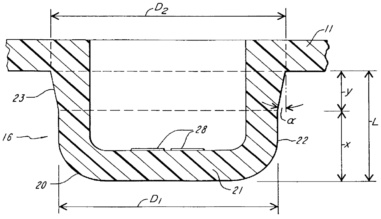
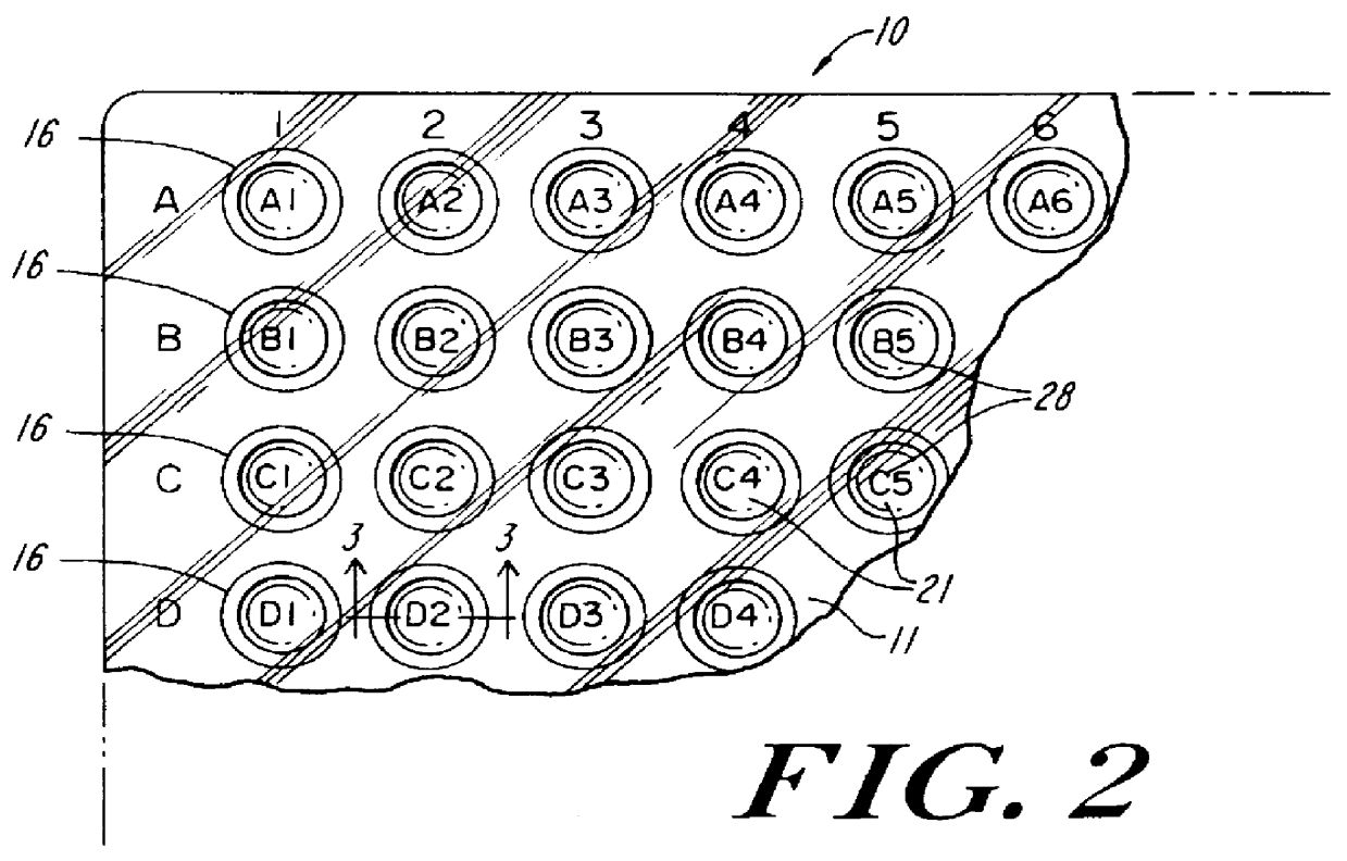
As can be best seen in FIG. 3, each cap 16 has a cup shaped nose 2...


PUM


Abstract

A closure device is provided which includes a flexible cover with an array of protruding hollow caps which are formed integrally with and depend from the cover. The caps have cup shaped noses with cylindrical side walls joined to the cover by inwardly tapered intermediate wall sections. The caps form a friction fit with an array of mutually spaced receptacles, for example test tubes, deep well blocks or microwell plates.

Description

1. Field of the InventionThis invention is directed to cap mats, cap strips and other like closure devices for plural laboratory receptacles such as test tubes, blocks and the like.2. Description of the Prior ArtVarious closure devices have been developed to seal test tubes and blocks. Some are relatively easy to apply and remove, but lack adequate sealing capability. Others provide a satisfactory seal but are extremely difficult to apply and remove, sometimes resulting in splashing and cross contamination of specimens contained in the receptacles. Additional drawbacks of conventional closure devices include an inability to function satisfactorily at elevated or reduced temperatures, and seal failures at differential pressures on the order of 0.5 atmospheres and below.The objective of the present invention is to provide a closure device which is not only relatively easy to apply and remove, but which is also capable of achieving a satisfactory seal under even the most demanding cond...

Claims


Application Information

Patent Timeline
Patent Type & Authority Patents(United States)
IPC IPC(8): B01L3/00B65D43/04
CPCB01L3/50853
Inventor SEGUIN, DANIEL J.BANAR, MARGARET M.
Owner MATRIX TECH
Why Eureka
Try Eureka