Microplate sample and reagent loading system

a microplate and reagent technology, applied in the direction of diaphragms, cell types, packaged goods, etc., can solve the problems of preventing its commercialization, no teaching respecting the use of pressure differential gradients, etc., to achieve enhanced efficacy, high speed, and low cost

Inactive Publication Date: 2002-01-17
AFFYMETRIX INC
View PDF15 Cites 35 Cited by
  • Summary
  • Abstract
  • Description
  • Claims
  • Application Information

AI Technical Summary

Benefits of technology

[0013] In contradistinction to each of these known systems, the teachings of the present invention embrace and finally address the clear need for a liquid transfer system which is operationally functional at high speed, low cost, and with an enhanced efficacy over conventional disclosures. This system also permits the accurate dispensing of extremely small submicroliter volumes.
[0018] Advantageously, the pressure driven fluid transfer system of the present invention has the benefit of performing low volume, uniform liquid transfer and liquid processing in parallel and is expandable to any number of capillaries. Likewise, the system has the capability of transferring solutions from one arbitrary reservoir configuration to another.
[0019] Briefly stated, there is provided a method and apparatus consisting of at least one capillary, a pressure box having first and second means for aligning the capillaries from one set of wells to a second set of wells, and applied pressure or pressure differential transfers small amounts of liquid uniformly and in parallel. A method of accurately controlling a desired volume of fluid flow is particularly useful for transferring liquids from a microtiter dish to a Capillary Array Electrophoresis Microplate having liquid wells spaced in a radially symmetric configuration

Problems solved by technology

However, owing to cost and the lack of flexibility of such systems numerous drawbacks have arisen.
This system addressed the need for application specific flexibility, but included a complex serving apparatus which impeded its commercialization.
However, there is no teaching respecting the use of pressure differential gradients, and their impact upon the forward and reverse transfer of fluids through the subject capillaries.

Method used


Image

  • Microplate sample and reagent loading system
  • Microplate sample and reagent loading system
  • Microplate sample and reagent loading system

Examples


Embodiment Construction

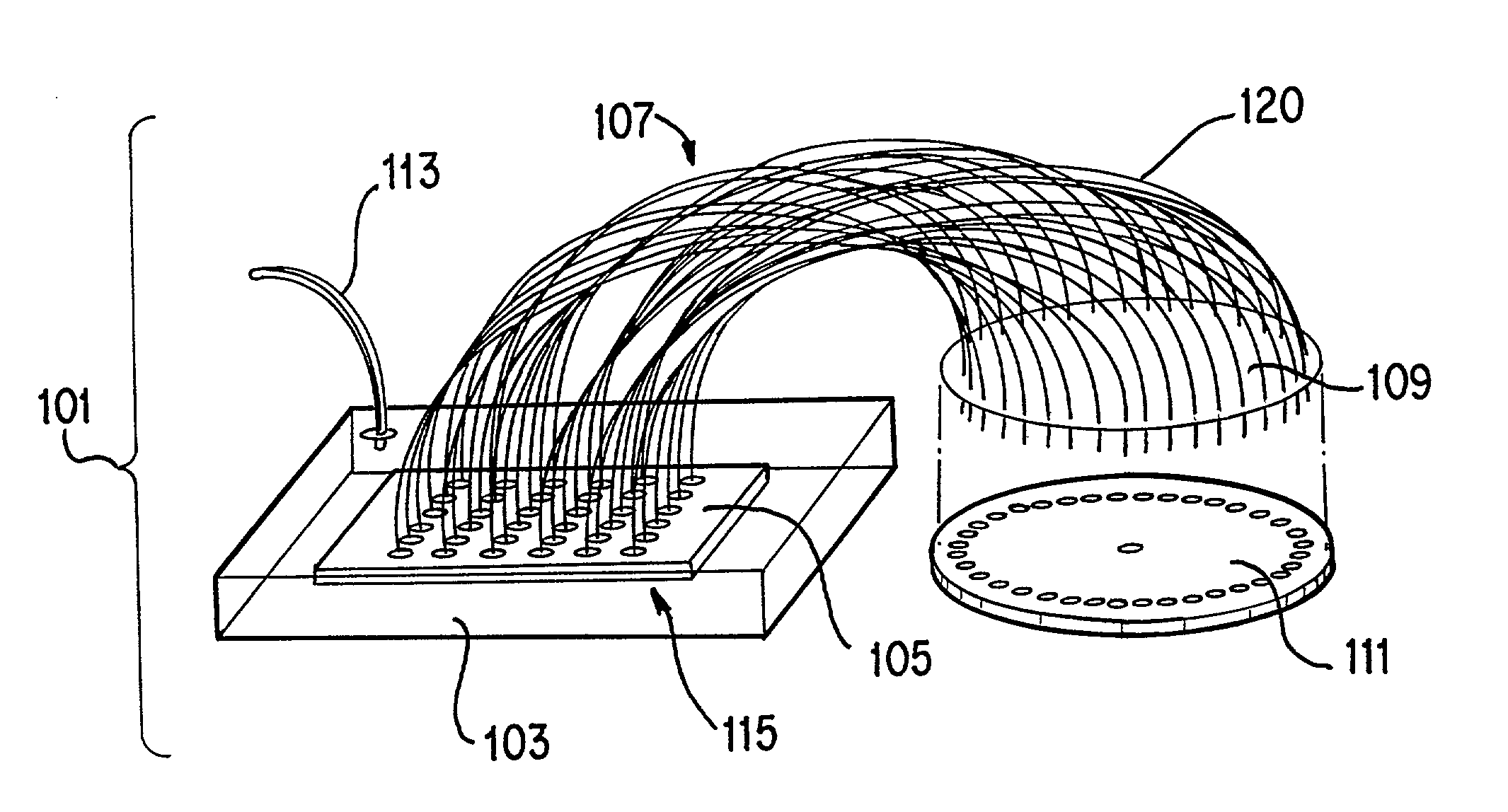
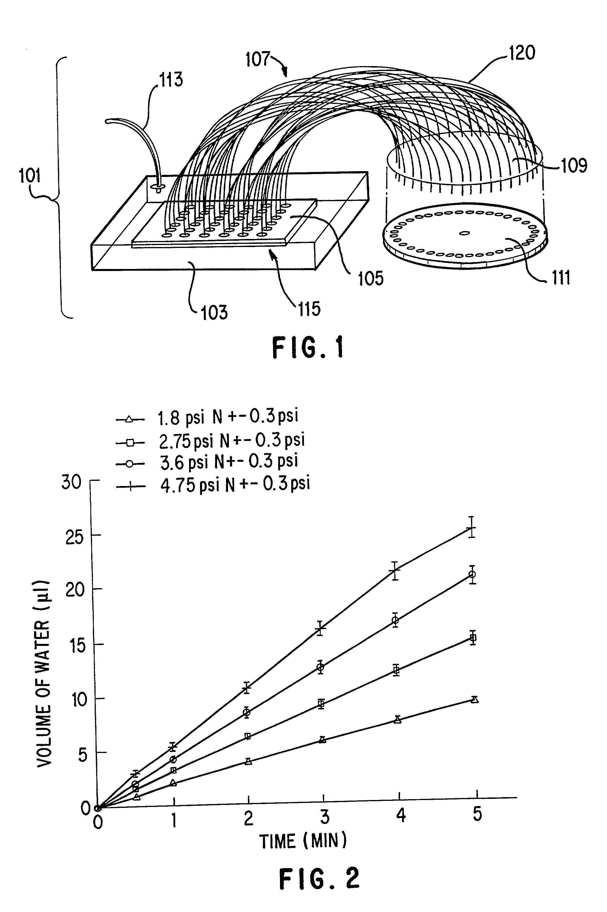
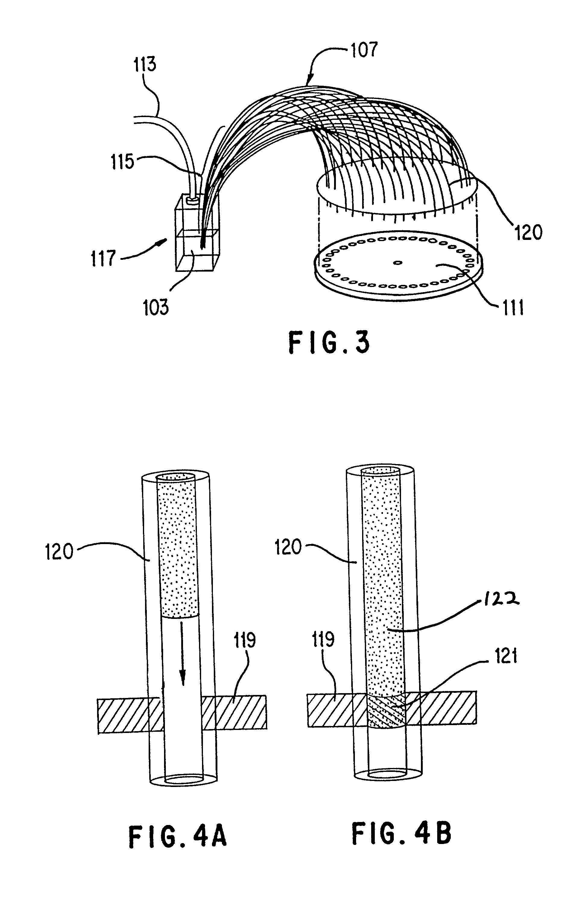
[0031] Heretofore undisclosed use of pressure differentials for the forward and reverse transfer of fluids through capillaries are disclosed according to the teachings of the present invention. Likewise, those skilled in the art will readily understand the utility of such teachings for use with rapidly evolving sampling technology for DNA and / or the like biomolecular species, compounds and / or substituent elements, moieties or structures.

[0032] The present inventors have discovered that preferred embodiments of present invention are utile in facilitating the revolution in separation science being effected by rapid and highly parallel electrophoretic analysis. (Simpson, P. C., Roach, D., Woolley, A. T., Thorsen, T., Johnston, R., Sensabaugh, G. F., & Mathies, R. A., 1998, 95 Proc. Natl. Acad. Sci. U.S.A. 2256-2261. Seiler, K., Harrison, D. J. & Manz, A. 1993 65 Anal. Chem., 1481-1488. This reference, and each other of the same cited herein, is expressly incorporated within the instant...


PUM

PropertyMeasurementUnit
pressureaaaaaaaaaa
lengthaaaaaaaaaa
timeaaaaaaaaaa

Abstract

Apparatus for forward and reverse transfer of fluids through capillaries, consisting of at least one capillary, a pressure generating or housing means, which preferably includes a box, having first and second means for aligning the capillaries from one set of wells to a second set of wells, and applied pressure differential transfers small amounts of liquid uniformly and in parallel. A method of accurately controlling a desired volume of fluid flow is particularly useful for transferring liquids to and from a microtiter dish to a Capillary Array Electrophoresis Microplate having liquid wells spaced in a radially symmetric configuration, or for maximizing desired transfer of the like or improved novel enhanced patterned arrays.

Description

[0002] 1. Area of the Art[0003] The present invention relates to methods and apparatus useful for small volume liquid transfer. In particular, the present invention relates to facilitating both forward and reverse parallel liquid transfer of aliquots of solutions from at least one reservoir, a set or array of reservoirs, to a different reservoir, set or array of reservoirs, as is especially useful in the context of systems for electrophoretic analysis, such as with Capillary Array Electrophoresis ("CAE") Microplates.[0004] 2. Description of the Prior Art[0005] Prominent among the conventional methods and apparatus for the transfer of liquids are robotic and the like automated systems. However, owing to cost and the lack of flexibility of such systems numerous drawbacks have arisen. Likewise, the trend toward automating and enhancing the efficiency of DNA mapping and sequencing technology has pushed the envelope of several related fields of art which have been synthesized serendiptio...

Claims


Application Information

Patent Timeline
Patent Type & Authority Applications(United States)
IPC IPC(8): B01L3/00B01L7/00B01L99/00F16K13/10F16L55/103G01N35/00G01N35/10
CPCB01L3/0293B01L3/563B01L2200/022B01L2300/0838B01L2300/1894Y10T436/2575B01L2400/0487B01L2400/0677G01N35/1074G01N2035/00267B01L2400/0406
Inventor MATHIES, RICHARD A.SIMPSON, PETER C.
Owner AFFYMETRIX INC
Why Eureka
Try Eureka