
Conductive microplate

a conductive microplate and micro-plate technology, applied in the field of conductive microplates, can solve the problems of increasing the likelihood of including other cell types, limiting the diffusion of arrays, and extending the hybridization time, so as to achieve fast and efficient binding and high probe biomolecule density

Inactive Publication Date: 2005-01-11
BECKMAN COULTER INC
View PDF27 Cites 37 Cited by
  • Summary
  • Abstract
  • Description
  • Claims
  • Application Information

AI Technical Summary

Benefits of technology

In view of the above-noted shortcomings of the conventional array systems, it is an object of the present invention to provide inexpensive array devices for fast and efficient binding of unamplified or amplified biomolecules. It is particularly desirable to provide inexpensive array devices having sufficiently high probe biomolecule density and suitable for HTS format of sample analysis. It is another object of the present invention to provide methods of making and using such array devices.
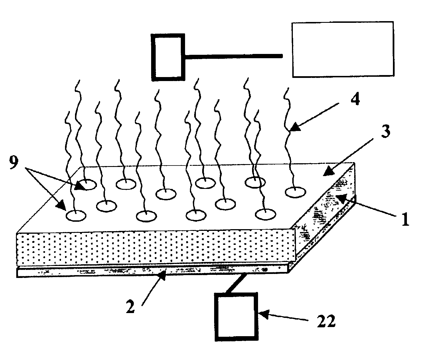
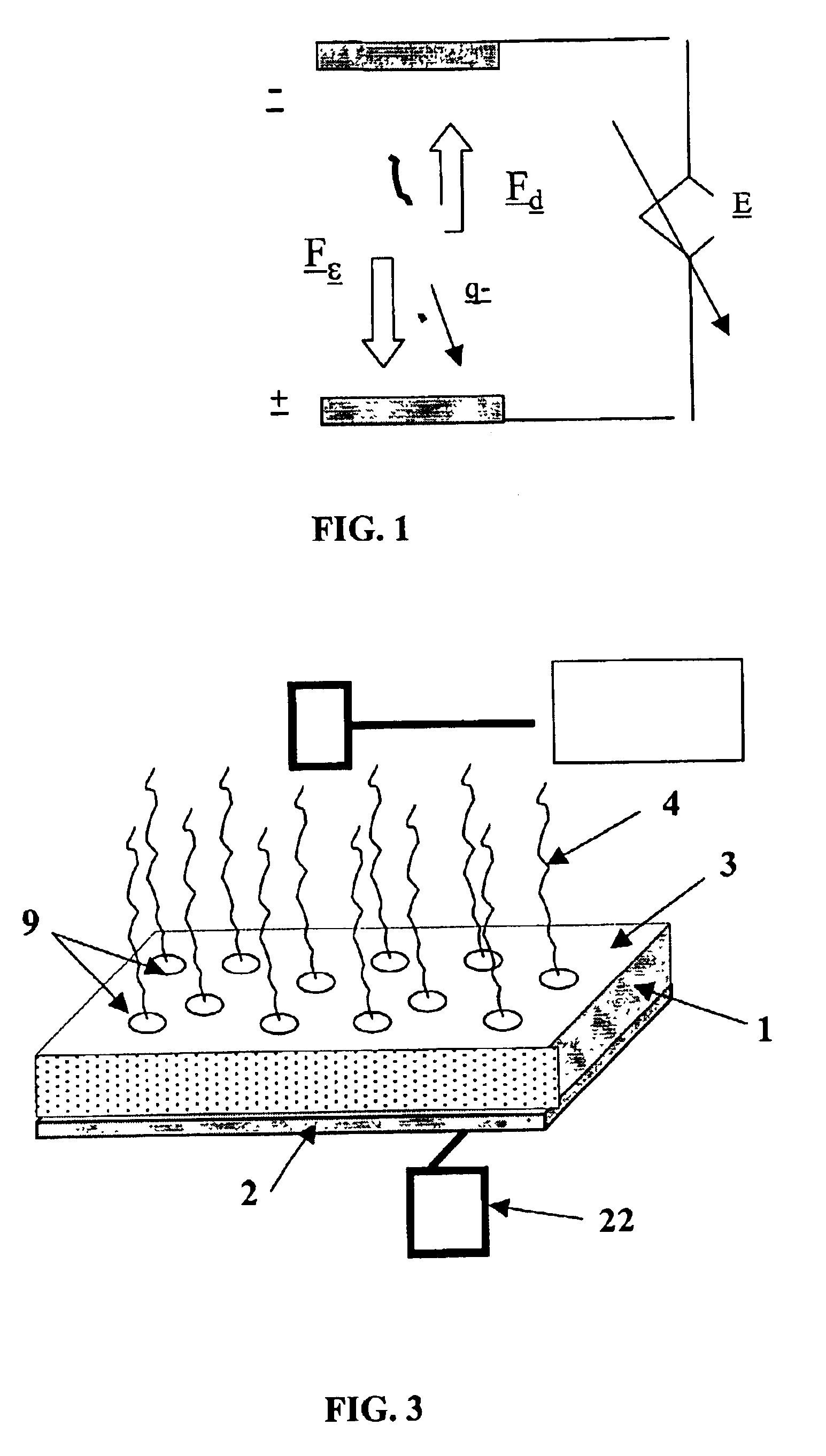
Another aspect of the present invention includes a device comprising the above-described conductive microplate and a power supply for supplying voltage to the microplate. Microplates of the present invention can be easily adapted for use with robotic workstations. Accordingly, in one embodiment, the power supply is incorporated into a robotic arm tool for fast microplate processing.
The microplates of the present invention, on the other hand, are constructed by activating and sealing an inexpensive porous conductive substrate into the bottom of microplate wells. Therefore, the conductive microplates of the present invention present an inexpensive, simple, and reliable alternative to conventional array devices.
Moreover, in a preferred embodiment of the present invention, a porous substrate is activated with acyl fluoride groups. Those skilled in the art will appreciate the advantages of acyl fluoride chemistry. Acyl fluoride groups are relatively resistant to reactions with water (“Peptide Synthesis via Amino Acid Fluorides,” Carpino, L., Beyerman, M., Wenschuh, H. & Bienert, M.: Acc. Chem. Res.: 29, 268-74, 1996), but are highly reactive with nitrogen and / or oxygen nucleophiles. This high reactivity combined with stability under aqueous conditions makes acyl fluoride activation chemistry particularly attractive to bioarray applications, because it provides an extended shelf life prior to and after immobilization of probe biomolecules. Finally, the acyl fluoride activated substrates can bind both modified and unmodified probe biomolecules. Since modification of biomolecules is not required, a substantial, up to 50%, reduction in the cost of reagents may be achieved.

Problems solved by technology

Although effective when dealing with samples of high volume and high target content, such arrays are diffusion-limited in samples with a low target concentration.
However, extending the hybridization time presents a serious bottleneck for high throughput and ultra high throughput sample processing.
The use of large cell populations may increase the likelihood of including other cell types that are not representative of the target biomolecule.
Additionally, amplification involves complex and lengthy procedures and can introduce significant bias by over-amplification of low abundant species.
Accordingly, cost, convenience, and flexibility limit the diffusion-based approach.
Although electronic array devices developed by Nanogen significantly increase the probe-target binding rate, these arrays do not lend themselves to high throughput screening (HTS) applications.
The electronic array devices of Nanogen are bulky, expensive, and difficult to control.
They also have a very limited probe biomolecule density and are not capable of processing thousands of samples per day as typically required by HTS.

Method used


Image

  • Conductive microplate
  • Conductive microplate
  • Conductive microplate

Examples


example 1

Activating Porous Substrate

Polypropylene substrate was surface functionalized with amine groups using a glowing gas chemical plasma process employing radio frequency plasma deposition or RFPD under conditions described in the commonly assigned U.S. Pat. No. 5,583,211. Surface amines were converted to carboxyl groups using succinic anhydride. The support was rinsed in solvent to remove moisture and allowed to dry. DAST reagent in anhydrous solvent (˜10% v / v) was applied to the support and incubated for 1-3 hours at ambient temperature in a dry, closed container. After the incubation, the support was rinsed in solvent and dried. Acyl fluoride-activated substrate was stored dry at −20° C. until needed.

example 2

Covalent Attachment of Probe DNA to the Activated Substrate

A solution of cDNA (20 nL of 1 nM stock solution in 50 mM sodium carbonate-bicarbonate buffer, pH 9) was printed on the surface of activated porous substrate prepared in accordance with Example 1. The printing was conducted using a Biomek 384-pin HDRT (high-density replicating tool). The printing was carried out without any modification of the cDNA. The cDNA-printed spots were allowed to react with the substrate for 1 hour in a humidified chamber held at 25° C. Active fluoride groups remaining on the surface were quenched in ethanol for 2 hours at ambient temperature. Biotin-labeled cDNA targets of actin, G3PDH, and TNF (e.g., 1 μl of a 41 nM stock solution diluted to a final volume of 150 μL; 41 fmoles applied ˜246×108 molecules) were hybridized (1 hour, 60° C., 2×SSC, 0.01% SDS) to the microarray. Subsequently, streptavidin-alkaline phosphatase conjugate was applied following rinsing; and signal was developed using ELF rea...

example 3

Electrophoresis Assisted Hybridization

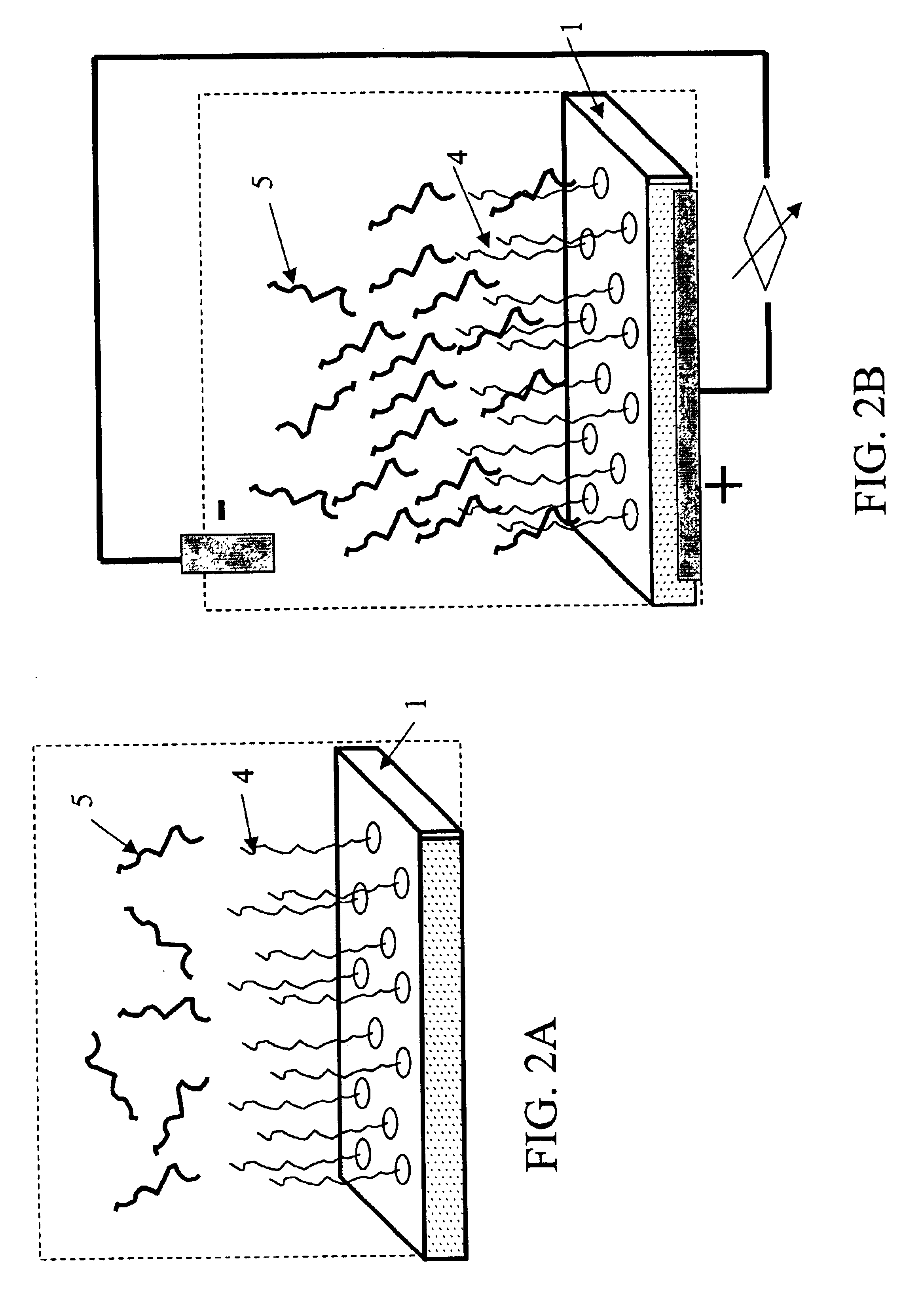
A porous membrane strip of ultra-high molecular weight polyethylene with cDNA probes immobilized on one side was mounted near the positive electrode of a slab gel electrophoresis apparatus. The strip was soaked with denaturant (0.5 M NaOH, 0.15 M NaCl) and incubated for 15 minutes. Residual denaturant was removed from the strip, which was then rinsed, and the electrophoresis apparatus flooded with running buffer (1×TBE). Target cDNA (actin) was boiled, then placed on ice and subsequently mixed with gel loading buffer (Digene Corp., Betsville, Md.) containing running dye. The cDNA target solution was placed approximately 0.5 cm away from the porous strip. Voltage was applied across the strip (274 V, 122 mA) and maintained for 5 minutes after the dye front had reached the strip. Power was turned off and hybridization was allowed to proceed for 5 minutes. The strip was removed from the apparatus and the signal developed using streptavidin-alkaline ...


PUM

PropertyMeasurementUnit
diameteraaaaaaaaaa
voltageaaaaaaaaaa
electricalaaaaaaaaaa

Abstract

A conductive microplate device for the detection of target biomolecules in a sample is described. The microplate comprises an assembly of a porous substrate and a conductive layer, wherein the assembly is sealed into bottom of at least some wells of the microplate. The porous substrate has a top surface and a bottom surface. The top surface comprises a plurality of covalently attached probe biomolecules. The covalently attached probe biomolecules are reactive with the target biomolecules contained in the sample. The conductive layer, which is attached to the bottom surface of the porous substrate, is adapted to receive voltage. Microplates of the present invention can be easily adapted for use with robotic workstations. Accordingly, in one embodiment, the power supply is incorporated into a robotic arm tool for fast microplate processing.

Description

AREA OF THE ARTThe present invention generally relates to devices for concurrently performing multiple assays. Specifically, the present invention relates to microplate devices containing active electrodes for the attraction of biomolecular target analytes. The invention also relates to methods of making and using such devices.DESCRIPTION OF THE PRIOR ARTMany contemporary methods of molecular biology, including nucleic acid hybridization analysis and protein binding analysis, utilize “biochips” or arrays of probe biomolecules (“probes”) to bind and detect target biological species (“targets”) in complex sample systems. Most commonly in these methods, a sample is simply placed onto the surface of the array and targets contained in the sample passively diffuse toward and bind with the probes immobilized on the support. Examples of commercially available microarrays utilizing passive diffusion principle include GENECHIP® arrays manufactured by Affymetrix (Santa Clara, Calif.) and GEM™ ...

Claims


Application Information

Patent Timeline
Patent Type & Authority Patents(United States)
IPC IPC(8): B01L3/00G01N33/53B01J19/00C12M1/00C12M1/34C12N15/09C12Q1/68C40B40/06C40B60/14G01N33/566G01N37/00
CPCB01J19/0046B01L3/50851Y10S435/817B01J2219/00585B01J2219/00596B01J2219/00639B01J2219/00653B01J2219/00659B01J2219/00677B01J2219/00722B01L2300/069B01L2300/0829B01L2300/1827B01L2400/0421C40B40/06C40B60/14B01J2219/00317
Inventor MATSON, ROBERT S.
Owner BECKMAN COULTER INC
Learn More