Scroll type fluid machine

a fluid machine and roller technology, applied in machines/engines, liquid fuel engines, positive displacement liquid engines, etc., can solve the problems of increased pressure in the operating pressure chamber of the bypass valve, reduced service life, and reduced service life of machines

Inactive Publication Date: 2000-10-31
DAIKIN IND LTD
View PDF6 Cites 45 Cited by
  • Summary
  • Abstract
  • Description
  • Claims
  • Application Information

AI Technical Summary

Problems solved by technology

Thus, the machine becomes inferior in manufacturability and reliability.
When such leakage takes place, loss of the performance increases.
When a liquid refrigerant of a non-compressive fluid or oil gets mixed into the fluid working chambers in large quantities, if a lag is caused in the timing for opening the two bypass holes AH and BH, and if the volume of the operating pressure chamber for the bypass valve opening earlier reduces, the pressure in the operating pressure chamber for the bypass valve delayed in opening operation increases, the opening operation is further delayed, and discharge of the liquid cannot be smoothly performed.

Method used


Image

  • Scroll type fluid machine
  • Scroll type fluid machine
  • Scroll type fluid machine

Examples


Embodiment Construction

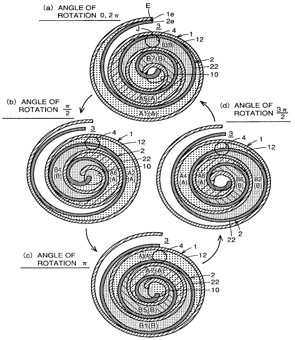
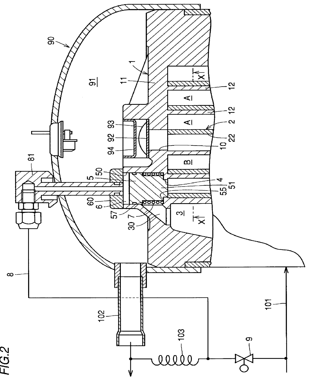
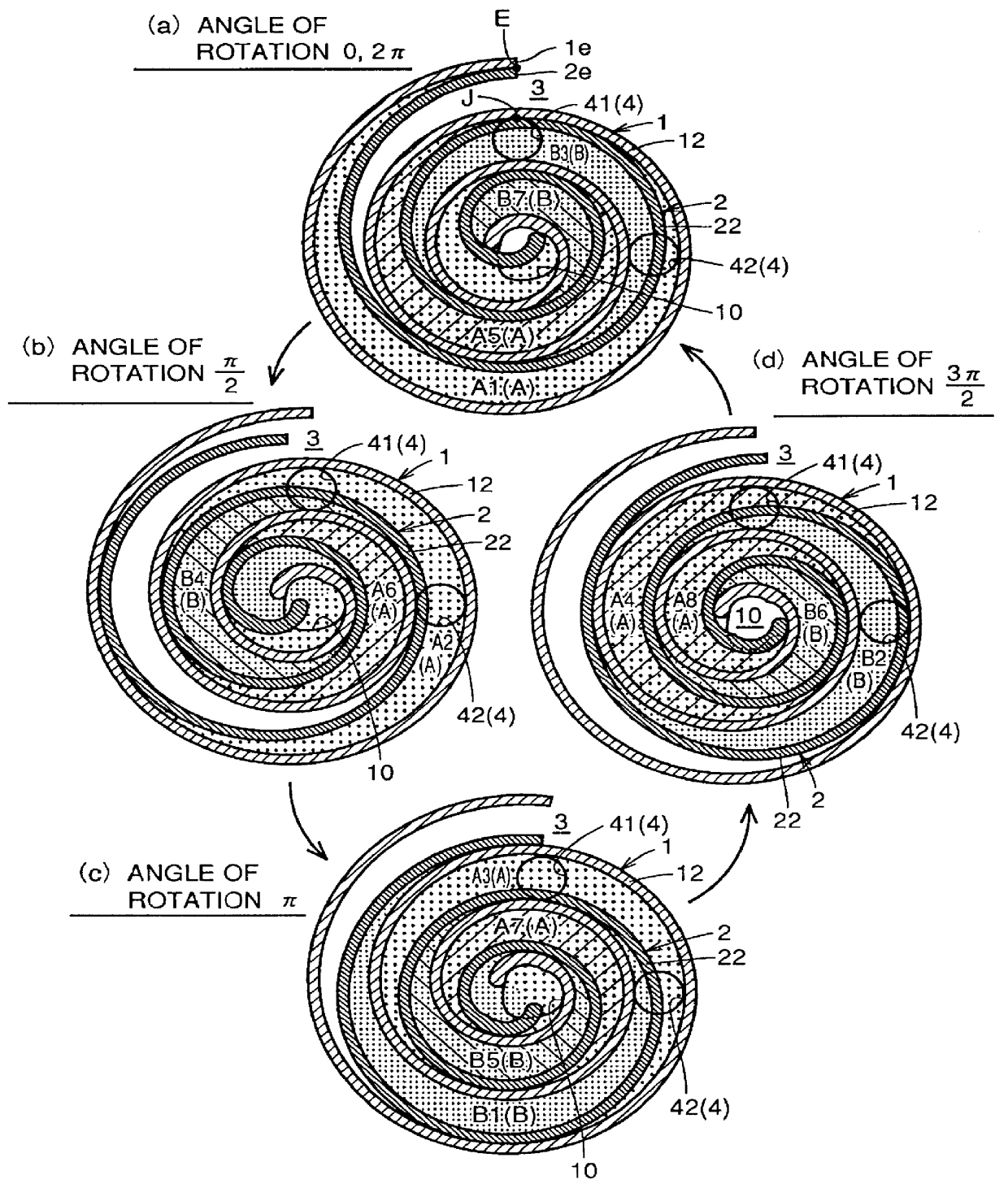
Referring to FIG. 1, a scroll type fluid machine according the present invention comprises a first scroll 1 having a first spiral blade 12, and a second scroll 2 having a second spiral blade 22 which is in sliding contact with the first spiral blade 12. In this embodiment, the first scroll 1 is a non-revolving scroll, and the second scroll 2 is a revolving scroll. First fluid working chambers A are formed between an inner surface of the first spiral blade 12 of the first scroll 1 and an outer surface of the second spiral blade 22 of the second scroll 2. Second fluid working chambers B of a different system from the first fluid working chambers A are formed between an outer surface of the first spiral blade 12 and an inner surface of the second spiral blade 22.

As shown in FIG. 1, the first fluid working chambers A are compressed in order of A1-A2-A3-A4-A5-A6-A7-A8. Similarly, the second fluid chambers B are compressed in order of B1-B2-B3-B4-B5-B6-B7.

In the embodiment shown in FIG. 1...


PUM


Abstract

PCT No. PCT/JP97/02013 Sec. 371 Date Nov. 3, 1998 Sec. 102(e) Date Nov. 3, 1998 PCT Filed Jun. 11, 1997 PCT Pub. No. WO98/57066 PCT Pub. Date Dec. 17, 1998A scroll type fluid machine having a bypass hole structure for capacity control is disclosed. The scroll type fluid machine comprises a first scroll having a first spiral blade, and a second scroll having a second spiral blade. A first fluid working chamber is formed between an inner surface of the first spiral blade, and a second scroll having a second spiral blade. A first fluid working chamber is formed between an inner surface of the first spiral blade and an outer surface of the second spiral blade, and a second fluid working chamber is formed between an outer surface of the first spiral blade and an inner surface of the second spiral blade. A winding end of the first spiral blade is extended so that the first fluid working chamber and the second fluid working chamber open and close with respect to a single low-pressure port. A common bypass hole making the first and second fluid working chambers communicate with the low-pressure port in common is provided.

Description

The present invention relates to a scroll type fluid machine which is mainly employed as a refrigerant compressor for an air conditioner or a refrigerator, and more particularly, it relates to a scroll type fluid machine having a bypass hole structure for capacity control.BACKGROUND TECHNIQUEA scroll type fluid machine having a bypass hole structure is disclosed in Japanese Patent Publication No. 2-55636, for example. In the scroll type fluid machine disclosed in this gazette, symmetrical fluid working chambers of two systems are formed between a pair of scrolls having symmetrical shapes, and bypass holes are provided in these fluid working chambers of the respective systems.FIG. 5 illustrates sectional views of the pair of scrolls of the aforementioned conventional scroll type fluid machine. The scroll type fluid machine comprises a non-revolving scroll F and a revolving scroll O. First fluid working chambers A are formed between an inner surface Fa of a spiral blade of the non-rev...

Claims


Application Information

Patent Timeline
Patent Type & Authority Patents(United States)
IPC IPC(8): F04C18/02F04C28/16F04C28/26F04C28/18F04C29/00F04C29/02F04C29/12F16K31/42
CPCF04C28/26F04C28/16F04C18/0215F04C18/0223
Inventor KUROIWA, HIROYUKIHAGIWARA, SHIGEKI
Owner DAIKIN IND LTD
Why Eureka
Try Eureka