Lithium secondary battery

a secondary battery and lithium battery technology, applied in the manufacture of final products, cell components, cell component details, etc., can solve the problems of large resistivity of the above-mentioned ptc element made of conductive particles and polymers, difficult to realize driving performance comparable to gasoline fueled vehicles, and large output loss

Inactive Publication Date: 2000-10-31
NGK INSULATORS LTD
View PDF13 Cites 103 Cited by
  • Summary
  • Abstract
  • Description
  • Claims
  • Application Information

AI Technical Summary

Problems solved by technology

However, since the lead acid storage battery itself is heavy and requires a large capacity, it has been difficult to realize driving performance comparable to a gasoline fueled vehicle.
However, for a large battery the resistivity of the above-mentioned PTC element made of the conductive particles and polymer is too large, about 1.OMEGA..multidot. cm at room temperature.
So the PTC element may cause the large output loss and the short lifetime.
Especially, in the case where such a PTC element is mounted on a large battery, concentration of current inside the PTC element is apt to occur due to the increase of an area of the element, which causes heat generation, so that the mounting to a large battery is difficult.
In addition, the PTC is generally expensive, and a large-sized one is not manufactured.
Further, it is thought that if a large battery is erroneously treated, the scale of accidents would become larger and the danger derived therefrom would also become higher than that imagined from a small battery.
For a large lithium secondary battery, this transition temperature about 130.degree. C. is too high.
In addition to such problems of the prior art, it is considered to be necessary to contrive means such that the resistance of an electricity generating portion itself is made small to widen the selection of materials of positive electrodes and negative electrodes.

Method used


Image

  • Lithium secondary battery
  • Lithium secondary battery
  • Lithium secondary battery

Examples


Embodiment Construction

Preferred embodiments of the present invention will next be described with reference to the drawings. However, it should be noted that the present invention is not limited to the embodiments described below.

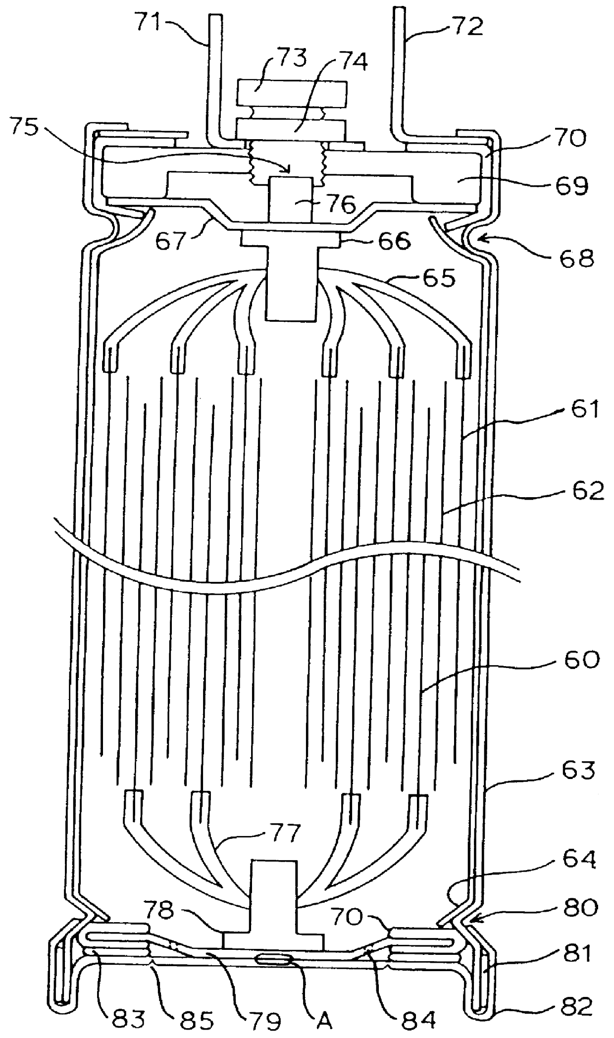
FIG. 1 is a sectional view showing an embodiment of a lithium secondary battery of the present invention. Positive electrode 60 and negative electrode 61 are insulated from each other through separator films 62, and these are wound to form an electricity generating portion. At this time, the positive electrode 60 and the negative electrode 61 are wound while the stacked position is shifted, so that they are easily connected to leads for collecting electricity. The thus produced electrode portion is inserted in a tube of aluminum as a battery case 63, and at this time, the inner surface of the battery case 63 is coated with a polyproplene film 64 to avoid direct contact with the electrode plates.

Here, as the positive electrode 60, an aluminum foil coated with lithium-cobalt oxide ...


PUM

PropertyMeasurementUnit
melting pointaaaaaaaaaa

Abstract

A lithium secondary battery includes an electricity generating portion in which positive electrode 60 and negative electrode 61 form a laminate through separator films 62 made of porous polymer so that the positive electrode 60 and the negative electrode 61 do not come in direct contact with each other, leads 65, 77 which are respectively connected to plural portions of the positive electrode 60 and the negative electrode 61 to make electricity collection, and a low melting point alloy member 76 as a current break mechanism being inserted in a current path of the inside of the battery, which is melted to break the current path when the temperature of the battery is raised over a predetermined temperature.

Description

BACKGROUND OF THE INVENTION AND RELATED ART STATEMENTThe present invention relates to a lithium secondary battery that can be easily manufactured, which has small internal resistance, and is provided with a safety mechanism for breaking a current at an abnormal time such as temperature rise in the battery due to over-charging / discharging.A lithium secondary battery has attracted a great deal of attention as a secondary battery that is small, which has a large energy density, and can be charged and discharged, and which can be used as a power source for an electric equipment such as a portable communication equipment and a notebook-sized personal computer, the electric equipment being rapidly downsized in recent years. Moreover, concerns for resource saving and energy saving are raised on the background of internationally protecting the earth environment, and this is one of the reasons why the lithium secondary battery is expected as a motor driving battery for an electric vehicle. F...

Claims


Application Information

Patent Timeline
Patent Type & Authority Patents(United States)
IPC IPC(8): H01M2/34H01M2/26H01M2/20H01M10/05H01M50/536H01M50/586
CPCH01M2/34H01M2/26Y02E60/10H01M50/572Y02P70/50H01M50/586H01M50/536
Inventor KUROKAWA, TERUHISANEMOTO, HIROSHI
Owner NGK INSULATORS LTD
Why Eureka
Try Eureka