Diaphragm with modified insert

a technology of inserts and diaphragms, which is applied in the direction of engine diaphragms, braking systems, machines/engines, etc., can solve the problems of diaphragms that tend to delaminate, further expense, and down time for the railroad

Inactive Publication Date: 2000-11-07
WESTINGHOUSE AIR BRAKE CO
View PDF2 Cites 47 Cited by
  • Summary
  • Abstract
  • Description
  • Claims
  • Application Information

AI Technical Summary

Benefits of technology

Therefore, it is one of the primary objects of the present invention to prov

Problems solved by technology

One problem with the present technology is that the diaphragm tends to delaminate at the periphery of the metallic insert because this is a stress concentration point which leads to dela

Method used


Image

  • Diaphragm with modified insert
  • Diaphragm with modified insert
  • Diaphragm with modified insert

Examples


Embodiment Construction

, particularly, when such detailed description is taken in conjunction with the attached drawing FIGS. and with the appended claims.

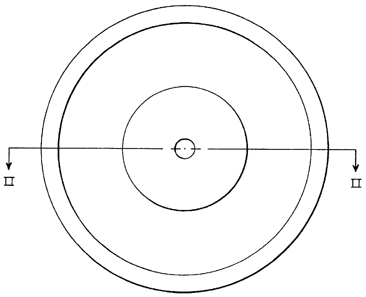
FIG. 1 is a plan view of a prior art diaphragm with an insert.

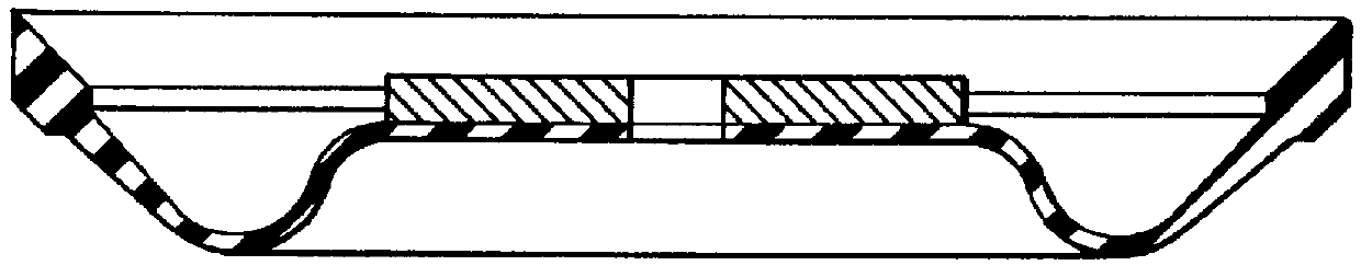
FIG. 2 is a cross-sectional view taken across the lines II--II of the prior art diaphragm with an insert shown in FIG. 1.

FIG. 3 is a plan view of a modified insert in an embodiment of the invention.

FIG. 4 is a cross-sectional view of the insert shown in FIG. 3 taken across the lines IV--IV.

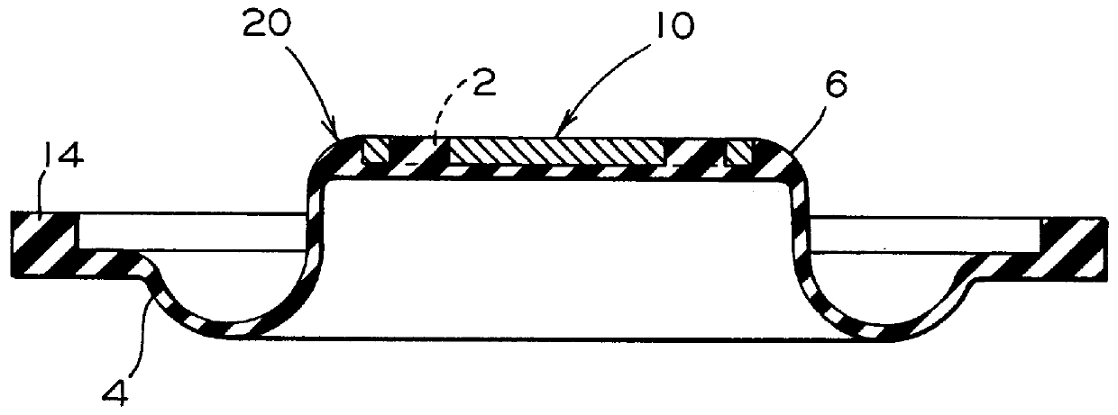
FIG. 5 is a cross-sectional view of the diaphragm with a modified insert in an embodiment of the invention.

FIG. 6 is a cross-sectional view of the diaphragm with a modified insert of the present invention shown in a limiting valve.

BRIEF DESCRIPTION OF THE PRESENTLY PREFERRED AND VARIOUS ALTERNATE EMBODIMENTS OF THE INVENTION

Prior to proceeding to the more detailed description of the various embodiments of the invention, it should be noted that, for both the sake of clarity and understanding of the improved ...


PUM


Abstract

The present invention provides a diaphragm member for use in certain valve assemblies. Such diaphragm member comprises a generally circular diaphragm having a first predetermined diameter and having a first surface and a second surface. Such generally circular diaphragm is formed from at least one layer of a preselected elastomeric material. Such generally circular diaphragm includes a nonflexing center portion, a generally annular flexure portion extending around an outer periphery of such nonflexing center portion and a non flexing outer portion extending around an outer periphery of such generally annular flexure portion, such non flexing outer portion is engageable with a body portion of such valve assembly. Such diaphragm member further includes a generally circular insert member, having a second predetermined diameter, disposed within the first surface of such nonflexing center portion of such generally circular diaphragm. Such generally circular insert member has a plurality of apertures formed through such generally circular insert member, such plurality of apertures provide a predetermined open area for receiving a predetermined rubber compound for bonding such generally circular insert member to such nonflexing center portion of such generally circular diaphragm.

Description

The present invention relates, in general, to a diaphragm used in valves and, more particularly, the present invention relates to a diaphragm with a modified insert for use in limiting valves in railway control valves.Control valves are an integral part of most railway freight cars. The control valve operates to control the flow of air to and from the brake cylinders and to charge the auxiliary and emergency reservoirs. An important part of such control valves are limiting valves.The service portion of such control valves contains two brake cylinder limiting valves which function to limit the maximum pressure directed to the brake cylinder application pipe or brake cylinder relay valve control pipe during service or emergency brake applications. The limiting valves are designated as the "Service Limiting Valve" and the "Emergency Limiting Valve". The maximum pressure output from these limiting valves is predetermined by load settings on the springs within each valve.Such limiting va...

Claims


Application Information

Patent Timeline
IPC IPC(8): B60T15/00B60T15/36F16J3/02F16J3/00
CPCF16J3/02B60T15/36
Inventor STREITMAN, LAWRENCE R.
Owner WESTINGHOUSE AIR BRAKE CO
Why Eureka
Try Eureka