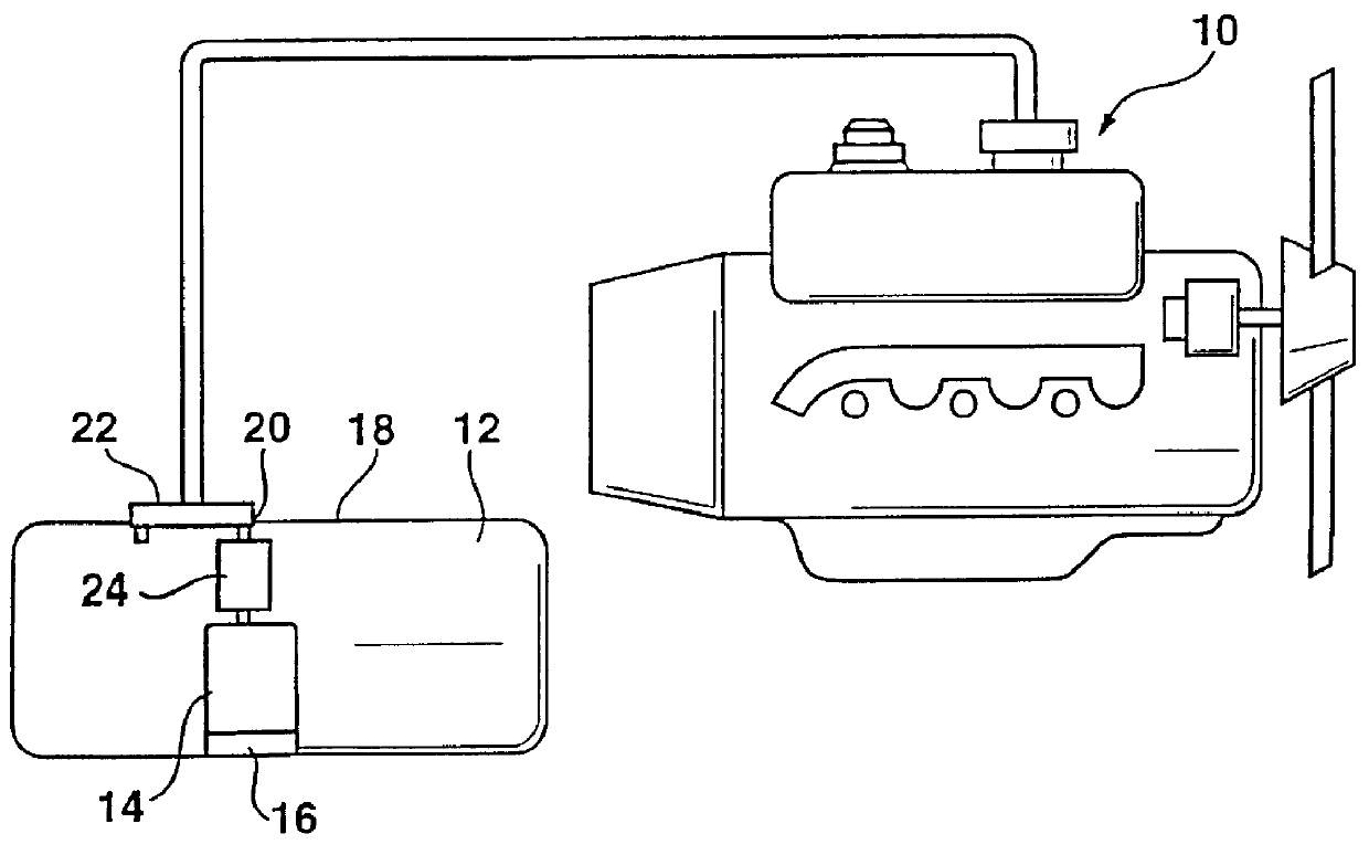
The device according to the invention for a
fuel supply system, has an
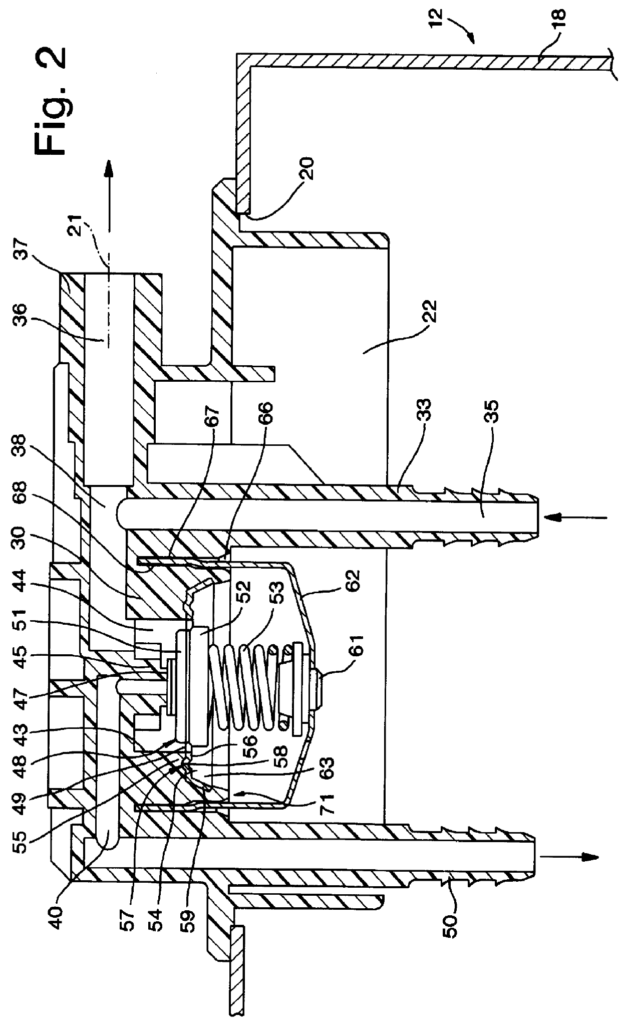
advantage over the prior art that simple, secure mounting of the diaphragm with regard to the basic body is accomplished with little effort or expense, and exact positioning of the diaphragm relative to the basic body can be attained. This enables a tight, durable connection with the basic body, and as a result the pressure chamber can be reliably partitioned off by the diaphragm. Because of the disposition of the spring ring on the basic body for fixing the diaphragm, it becomes possible for the clamping force of the prestressed spring ring, which is disposed relative to the basic body and retains the diaphragm, to be determined only by the initial tension of the spring ring. This arrangement also has the
advantage that once the diaphragm has been positioned relative to the basic body, fastening of the diaphragm relative to the basic body is made possible by simply placing the spring ring in place, which preferably engages the
peripheral region of the diaphragm, and twisting forces or other forces that cause shifting or impairment of the position of the diaphragm relative to the basic body cannot occur. In addition, the spring ring that fixes the diaphragm relative to the basic body has the
advantage that because of the resilient arrangement or the arrangement with initial tension, and
equalization of tolerance is possible, thus providing a secure disposition of the diaphragm relative to the basic body. It is also advantageous that in the device embodied according to the invention, first the diaphragm is firmly braced against the basic body before a spring that presses against the diaphragm is put in place. This prevents the spring from undesirably shifting the diaphragm toward the side.
In the proposed device, the stub through which the fuel return extends can be injection molded together with the basic body as a plastic part, using an injection molding tool. This has the advantage that in the production of the basic body, no additional effort or expense is needed to produce the stub.
In an advantageous embodiment of the invention, it is provided that the clamping element is embodied as a cup-springlike ring. By means of this
metal ring, the
diameter that defines the
effective surface area of the diaphragm toward the outside can be determined, and as a result an increase in the effective area of the diaphragm during use of the device is prevented; such an increase, if the diaphragm is used in a
pressure regulator, could be expressed in a drop in the regulated pressure.
Especially if the device is disposed with the diaphragm outside a
fuel tank, it is absolutely important that the pressure chamber of the device remain tightly sealed off from the outside during the entire service life of the device. By means of the elastic prestressing of the installed spring ring, the advantage is attained that the diaphragm is pressed against the basic body with sufficient force even over a relatively long
operating time of the device, regardless of any
settling of the preferably plastic basic body.
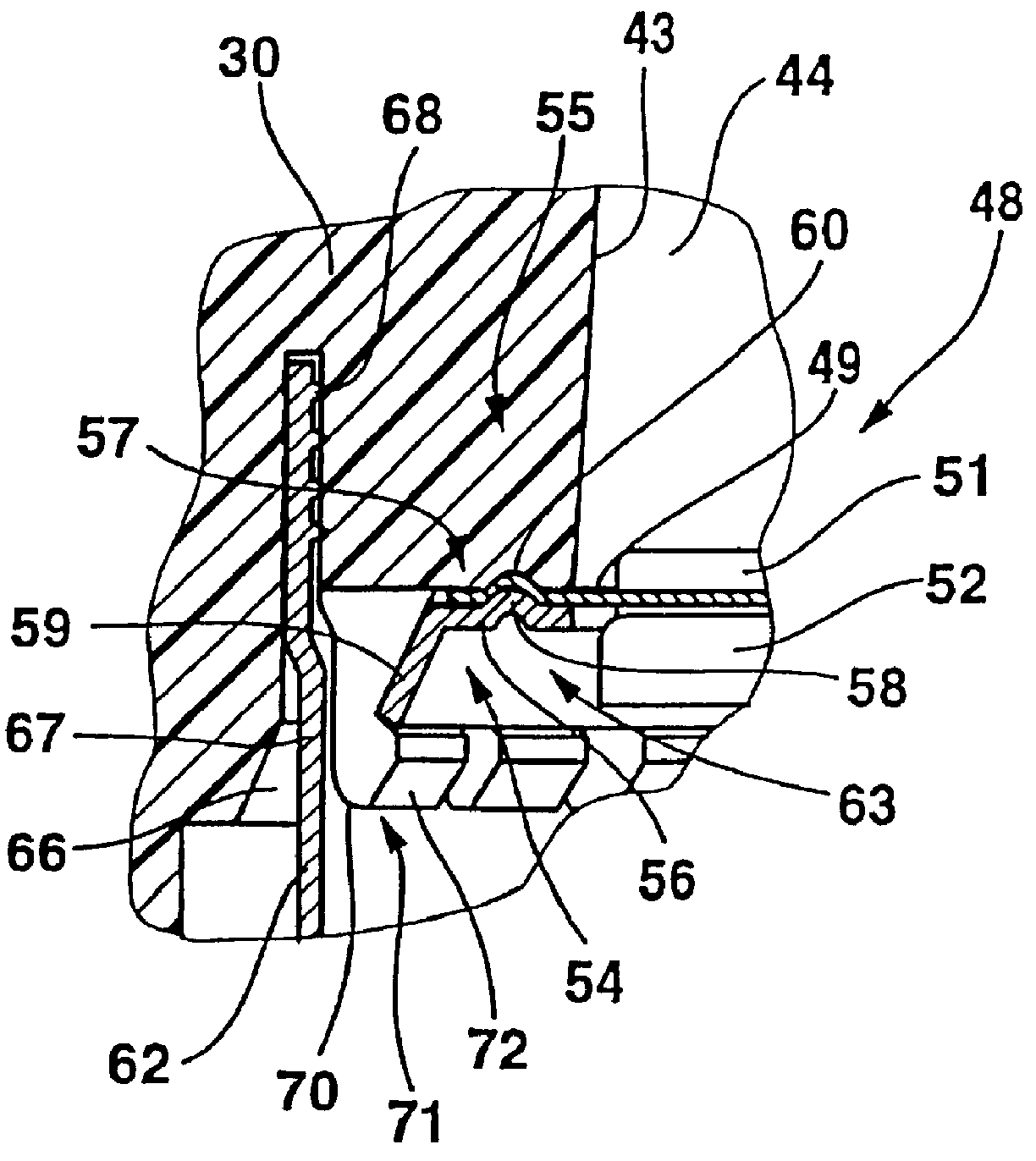
In another advantageous embodiment of the invention, it is provided that the spring ring, in the region where it is fastened in place, has a camlike lobe pointing toward the diaphragm, that engages an indentation, formed congruently in the basic body, of the fastening point. As a result, this makes an additional improvement possible in that when the diaphragm is deflected upon excessive pressure in the pressure chamber, the diaphragm is securely held in its position in the fastening point. By means of this fastening, it can also be assured that an increase in the sealing relative to the pressure chamber is accomplished.
In another advantageous feature of the invention it is provided that the spring ring acting as a clamping element has an annular collar on its free ends, so that the spring ring is cup-shaped in cross-section. As a result, an increase in the clamping force can be attained when the cup-springlike ring is disposed on the basic body. Because of the virtually perpendicularly embodied receptacle for the spring ring, the cup-springlike ring, whose portions forming the cuplike cross section are disposed at an angle of more than 90.degree., can exert an additional clamping force on the portion disposed in the fastening point, because the portion forming an annular collar can exert an additional force on the portion oriented toward the diaphragm.
In another advantageous feature of the invention it is provided that the spring ring can be inserted into the recess freely from above and secured with initial tension. This can advantageously be accomplished via a detention connection. It can also advantageously be provided that a springlike annular element, in particular a snap ring, can be inserted into a groove provided on the basic body. It can also advantageously be provided that the free ends of the basic body adjoining the recess, a fastening in place of the diaphragm and disposition of the spring ring with initial tension can be provided by deformation, such as crimping, caulking or the like.

