Heavy duty pneumatic radial tires with specified belt cushion rubbers

a technology of belt cushion rubber and radial tire, which is applied in the direction of textiles and paper, vehicle components, yarn, etc., can solve the problems belt end separation failure, and inconvenience of facilitating the occurrence of belt end separation failur

Inactive Publication Date: 2000-11-14
BRIDGESTONE CORP
View PDF1 Cites 16 Cited by
  • Summary
  • Abstract
  • Description
  • Claims
  • Application Information

AI Technical Summary

Benefits of technology

In the pneumatic radial tire according to the invention, (1) a pair of cushion rubbers are arranged between the adjoining rubberized cord layers constituting the main cross belt at their both end portions; (2) mutual cushion rubbers arranged at each belt end and most approaching to each other in a widthwise direction of the tire among these cushion rubbers are partly overlapped with each other in the widthwise direction of the tire; and (3) a distance d between ends of such mutual cushion rubbers facing an equatorial line of the tire in the widthwise direction of the tire is not less than 1.5% of a section width W of the main cross belt, so that it is particularly effective to control the progress of the separation failure created at the belt end toward the inside of the tire.
When a load is applied to the tire, a maximum load is usually produced in the vicinity of the equatorial plane of the tire, whereby rubber is moved from a central side toward a shoulder side of the tire and the movement of rubber toward the shoulder side at the belt end is particularly large and hence the interlaminar shearing strain in the rotating axial direction of the tire becomes large. Such a large interlaminar shearing strain in the rotating axial direction promotes the progress of the separation failure produced at the belt end toward the inside of the tire.
In the pneumatic radial tire according to the invention, the distance d between the ends of the mutual cushion rubbers facing an equatorial line of the tire in the widthwise direction of the tire is sufficiently large and is not less than 1.5% of the section width W of the main cross belt as previously mentioned. The rubberized cord layers arranged adjacent to these cushion rubbers at the outside and inside thereof in the radial direction do not push up to each other. Therefore, the movement of rubber at the belt end is controlled and also the progress of the belt end separation failure toward the inside of the tire is controlled. Furthermore, the aforementioned phenomenon that the belt end is compressed in the radial direction to push up the end portion of the cushion rubber facing the equatorial line through the action of lever is hardly caused.

Problems solved by technology

In general, it is apt to cause separation failure at belt end in the heavy duty pneumatic tires representing a pneumatic tire for construction vehicle provided with the main cross belt as mentioned above.
This separation failure at belt end is caused by rubber fatigue at the belt end due to interlaminar shearing strain based on an air pressure of the tire and dynamic interlaminar shearing strain applied by load applied to the tire, driving force, braking force, lateral force and the like.
As a result, the shearing strain between the rubberized cord layer constituting the main cross belt and the cushion rubber at the belt end is rather increased and there may frequently be caused an inconvenience of facilitating the occurrence of the belt end separation failure.
And also, the belt end is compressed in the radial direction to push up the end portion of the cushion rubber facing the equatorial line through the action of lever, whereby the progress of the separation failure is promoted toward the inside of the tire and as a result, there may be caused the separation failure even at this position under a certain circumstance.

Method used


Image

  • Heavy duty pneumatic radial tires with specified belt cushion rubbers
  • Heavy duty pneumatic radial tires with specified belt cushion rubbers
  • Heavy duty pneumatic radial tires with specified belt cushion rubbers

Examples


Embodiment Construction

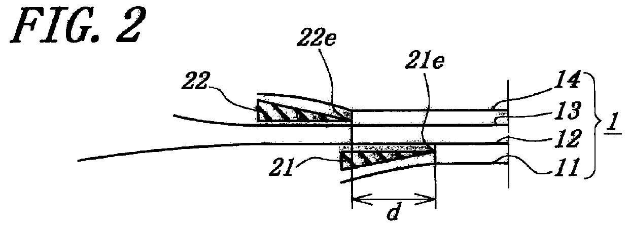
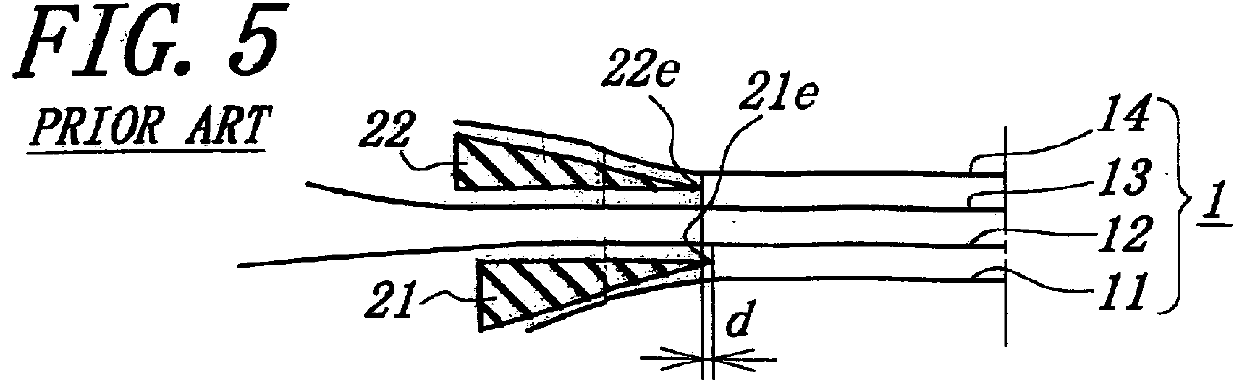
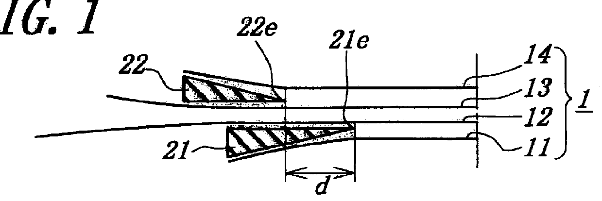
FIGS. 1 to 4 show various embodiments of the main cross belt arrangement in the pneumatic radial tire for construction vehicle according to the invention, while FIG. 5 shows the main cross belt arrangement of the conventional pneumatic radial tire. Each of these tires has a tire size of 37.00R57.

A tire of Example 1 shown in FIG. 1 comprises a pair of bead cores (not shown) embedded in a pair of bead portions, a radial carcass (not shown) of a rubberized cord ply extending between the bead cores and turned around each bead core from inside of the tire toward outside thereof, a belt superimposed about a crown portion of the carcass on an outer peripheral surface thereof and comprised of a main cross belt 1 and a tread portion (not shown).

The main cross belt 1 is formed by laminating four rubberized cord layers 11, 12, 13, 14 each containing a plurality of substantially inextensible steel cords having an elongation at break of 2% and embedded in a coating rubber so that the cords in ea...


PUM

PropertyMeasurementUnit
elongation at breakaaaaaaaaaa

Abstract

A heavy duty pneumatic radial tire comprises a radial carcass, a main cross belt and a tread portion, in which the main cross belt is formed by laminating at least three rubberized cord layers so that the cords in each layer are parallel to each other but the cords between the adjoining layers are crossed with each other and extend in opposite directions with respect to an equatorial line of the tire. In such a tire, a pair of cushion rubbers are arranged between the adjoining rubberized cord layers constituting the main cross belt at their both end portions by setting a position relation between mutual cushion rubbers at both belt ends to an optimum value to thereby prevent or control the occurrence of the belt end separation failure.

Description

1. Field of the InventionThis invention relates to a heavy duty pneumatic radial tire, and more particularly to a heavy duty pneumatic radial tire comprising a radial carcass of a rubberized cord ply extending between a pair of bead cores and turned around each bead core from inside of the tire toward outside thereof. A belt is superimposed about a crown portion of the carcass on an outer peripheral surface thereof and comprised of a main cross belt and a tread portion, in which the main cross belt is formed by laminating at least three rubberized cord layers each containing a plurality of substantially inextensible metal cords therein so that the cords in each layer are parallel to each other but the cords between the adjoining layers are crossed with each other and extend in opposite directions with respect to an equatorial line of the tire.2. Description of Related ArtIn general, it is apt to cause separation failure at belt end in the heavy duty pneumatic tires representing a pn...

Claims


Application Information

Patent Timeline
Patent Type & Authority Patents(United States)
IPC IPC(8): B60C9/18B60C9/20
CPCB60C9/20B60C9/18
Inventor YAMADA, SEIJINAKATA, HIROSHI
Owner BRIDGESTONE CORP
Why Eureka
Try Eureka