Liquid crystal panel and display including dichroic dye for absorbing yellow component of incident light

a liquid crystal display and dichroic dye technology, applied in the direction of identification means, instruments, chemistry apparatus and processes, etc., can solve the problems of color yellow, contrast which cannot be obtained, and high contrast in the conventional tn mode liquid crystal panel

Inactive Publication Date: 2000-11-14
SHARP KK
View PDF10 Cites 28 Cited by
  • Summary
  • Abstract
  • Description
  • Claims
  • Application Information

AI Technical Summary

Problems solved by technology

Due to this fact, a high contrast cannot be realized in the conventional TN mode liquid crystal panel.
As a result, a very high contrast can be obtained in such a VA mode liquid crystal panel, a level of contrast which cannot be obtained by a TN mode liquid crystal panel.
However, the VA mode liquid crystal panel has a problem that it is colored yellow when observed from an upper oblique direction.
However, the display contrast of the panel deteriorates as the retardation of the panel decreases, thus reducing the brightness of the panel.
In this case, however, the display co

Method used


Image

  • Liquid crystal panel and display including dichroic dye for absorbing yellow component of incident light
  • Liquid crystal panel and display including dichroic dye for absorbing yellow component of incident light
  • Liquid crystal panel and display including dichroic dye for absorbing yellow component of incident light

Examples


second example

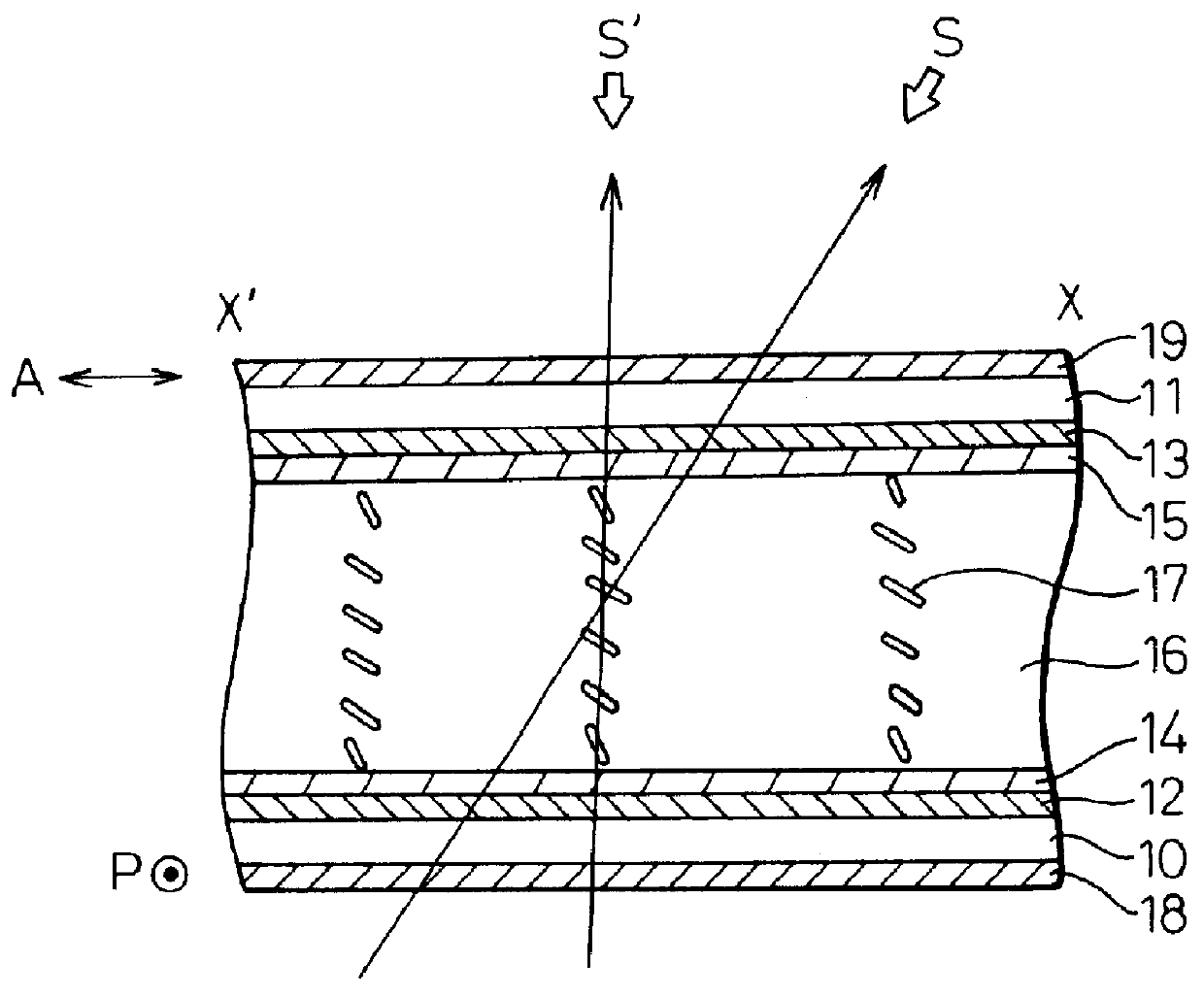
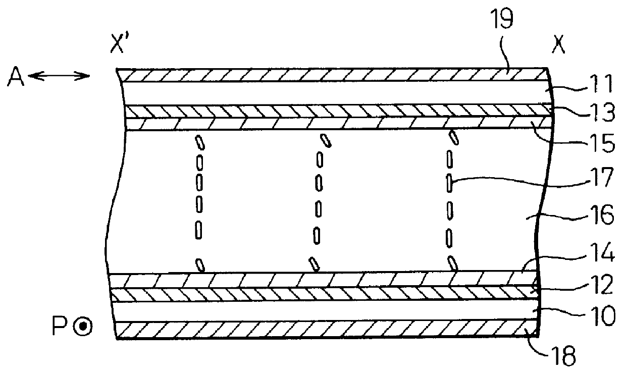
FIGS. 16 and 17 show the second example of a pixel portion of the liquid crystal panel, which is of an active matrix type, according to the present invention. FIG. 17A is a cross sectional view along line II-II' shown in FIG. 16 in the absence of applied voltage and FIG. 17B is the same view as that of shown in FIG. 17A in the presence of applied voltage. In FIG. 16, the same numerals as those shown in FIG. 14 denote the same or similar structure elements. However, the pixel shown in FIG. 16 differs from that shown in FIG. 14 in the rubbing structures of the alignment films provided on the TFT substrate and the common substrate.

As shown in FIGS. 16A and 16B, one pixel is divided into two regions (i) and (ii) whose alignment directions differ from each other. This structure is called an alignment division. Although various methods are known to accomplish the alignment division, the present example forms the two regions by changing the rubbing directions of these regions.

In actuality,...


PUM


Abstract

A liquid crystal panel has a pair of substrates disposed almost parallel to each other. On each of the substrates, an electrode and an alignment film are formed. A liquid crystal layer having a negative dielectric anisotropy is sandwiched by the substrates. In the absence of voltage applied across the electrodes, the molecules of the liquid crystal layer align almost perpendicular to the substrates. In this liquid crystal layer, a dichroic dye, preferably a blue dichroic dye, is added to absorb the yellow component of an incident light. Instead of adding the dye into the liquid crystal layer, a color compensation layer containing the dye is formed on or adjacent to at least one of the substrates. The yellow component of an incident light to the liquid crystal panel is absorbed by the color compensation layer. As a result, the liquid crystal panel and the liquid crystal display using the panel do not show yellow coloring when the panel is observed from oblique directions.

Description

1. Field of the InventionThe present invention relates to a liquid crystal panel and a liquid crystal display using the panel. In particular, it relates to a liquid crystal panel and a liquid crystal display which is driven in a mode which aligns liquid crystal molecules having a negative dielectric anisotropy almost perpendicular to the substrates of the panel in the absence of applied voltage (vertical aligned mode, referred to as VA mode below).2. Description of the Related ArtLiquid crystal displays are used widely as a display for various information processing devices, such as computers and TVs.In a conventional liquid crystal display, a liquid crystal panel of a TN type, an STN type or a TFT type etc. is widely used in a mode which aligns the liquid crystal molecules having a positive dielectric anisotropy, i.e., a p type liquid crystal, parallel to the substrates opposed to each other in the absence of applied voltage.In a liquid crystal panel of a TN mode, for example, the ...

Claims


Application Information

Patent Timeline
IPC IPC(8): G02F1/13G02F1/139G02F1/1335G02F1/137C09K19/60G02F1/1337G09F9/35
CPCG02F1/13725G02F1/133514G02F2202/04G02F2001/13712G02F1/1393G02F1/13712G02F1/1337
Inventor YOSHIDA, HIDEFUMIOHMURO, KATSUFUMI
Owner SHARP KK
Why Eureka
Try Eureka