Method and mechanism for dynamic trim of a fast moving, planning or semi-planning ship hull

Inactive Publication Date: 2000-11-21
MARINE TECH DEV
View PDF9 Cites 40 Cited by
  • Summary
  • Abstract
  • Description
  • Claims
  • Application Information

AI Technical Summary

Benefits of technology

is to provide methods and mechanisms for dynamic trim of a fast moving, planing or semi-planing ship hull, the implementation of which will set aside the mentioned draw

Problems solved by technology

Also, the use of dual hydro foils calls for complex mechanisms for controlling the operation of the

Method used


Image

  • Method and mechanism for dynamic trim of a fast moving, planning or semi-planning ship hull
  • Method and mechanism for dynamic trim of a fast moving, planning or semi-planning ship hull
  • Method and mechanism for dynamic trim of a fast moving, planning or semi-planning ship hull

Examples


Embodiment Construction

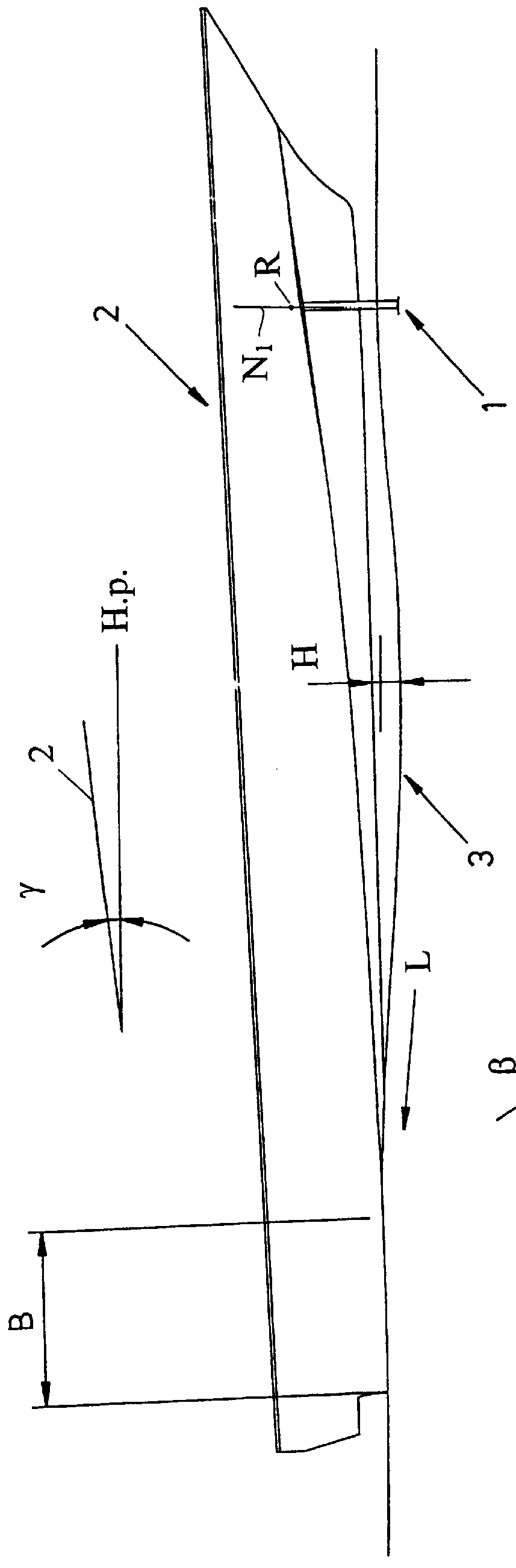
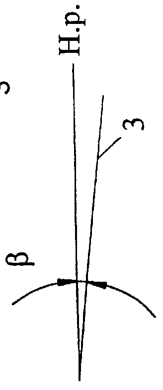
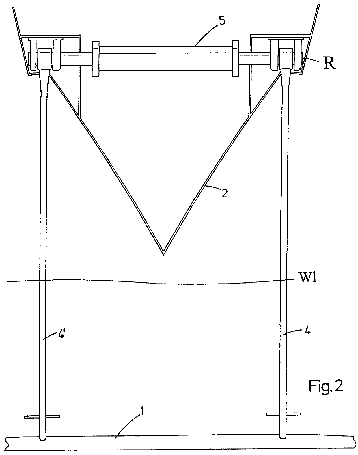
The invention is based on the concept of using a fully submerged support plane or hydro foil 1 that is pivotally arranged in a stern portion of a ship hull 2, as shown in FIG. 1. The hydro foil 1 is specifically designed to control the shape of a wave 3 generated by the hydro foil 1 during propulsion of the ship. The wave 3 is controlled to have a predetermined length, width and depth that causes the water to engage the rear portion of the bottom of the ship hull at an advantageous angle of intersection, providing thereby additional and, at varying speeds optimum lift power to the stern of the ship. The ship hull's contact area with the water surface typically corresponds to about 5-20% of the length of the bottom of the ship hull at varying speeds, see B in FIG. 1. By controlling the shape of the wave, it is possible to take full advantage of the lifting powers of the wave to reduce the frictional drag of the ship hull, resulting in lower construction and propulsion costs and less ...


PUM


Abstract

A mechanism and method for dynamic trim of the floating position of a fast moving, planing or semi-planing ship hull is suggested, wherein a fully submerged hydro foil (1) is pivotally arranged in a stem portion of the ship and continuously adjustable relative to the angle of attack of the hydro foil for generating a wave, the wave having a length, a width and a depth related to the length, the tonnage and the cruising speed of the ship, wherein the hydro foil is designed relative to the wave so that the wave width is controlled by a span width (a), the wave length is controlled by a chord length (b), and the wave depth is controlled by a load (p) of the hydro foil.

Description

The present invention relates to methods and mechanisms for continuous control and trim of the floating position of a fast moving, planing or semi-planing ship hull during acceleration and propulsion at cruising speed.The need for higher speeds during sea transportation has lately produced a plurality of technical improvements. The primary goal of these improvements has been to reduce the drag during the forward propulsion of the ship, and thus the need for power at higher speeds. Some of these improvements have in common that the wet surface is reduced, and therefore the frictional drag is reduced. "Wet surface" as referred to herein should be understood as the part of the ship hull that is in contact with the water surface or the part that is submerged below the water surface.Beside the need for higher speeds, there is also a growing need for improved comfort of passengers.Conventional fast moving and planing typically have the center of gravity positioned aft of the mid section o...

Claims


Application Information

Patent Timeline
IPC IPC(8): B63B39/00B63B1/16B63B39/06B63B1/24
CPCB63B1/24B63B39/061Y02T70/12B63B2001/325Y02T70/10
Inventor PAVLOV, STANISLAV D.PORODNIKOV, SERGUEJ A.NORRSTRAND, CLASERIKSSON, HANS
Owner MARINE TECH DEV
Why Eureka
Try Eureka