Arc evaporator and method for operating the evaporator

Inactive Publication Date: 2011-12-29
FUNDACION TEKNIKER
View PDF4 Cites 5 Cited by
  • Summary
  • Abstract
  • Description
  • Claims
  • Application Information

AI Technical Summary

Problems solved by technology

If some type of control is not applied on the movement of the arc, said movement can be random, causing a non-homogeneous wear of the cathode, which can entail a poor exploitation of the material of the cathode, the unit cost of which can be quite high.
However, for larger-sized evaporators, the problem becomes increasingly more important.
On the other hand, these magnetic steering elements contribute to increasing the reliability of the arc evaporator, since they make it impossible or difficult for the arc to accidentally move to a point that is not part of the evaporation surface.
A problem of this machine is that the magnetic system of mobile permanent magnets is very mechanically complex and therefore expensive to implement and susceptible to breakdowns.
As in the case of the systems described in U.S. Pat. No. 4,724,058 and other similar ones, a problem with the system described in U.S. Pat. No. 5,298,136 is that the magnetically defined path cannot move over the surface of the evaporation target (or it does so in a very small range), so in order to achieve a wear which is not excessive on that path it is necessary to limit the intensity of the magnetic field to allow the arc to have a certain freedom to move away from the pre-established path.
On the contrary, when the magnetic steering element is of the steered arc technology type, in which

Method used


Image

  • Arc evaporator and method for operating the evaporator
  • Arc evaporator and method for operating the evaporator
  • Arc evaporator and method for operating the evaporator

Examples


Embodiment Construction

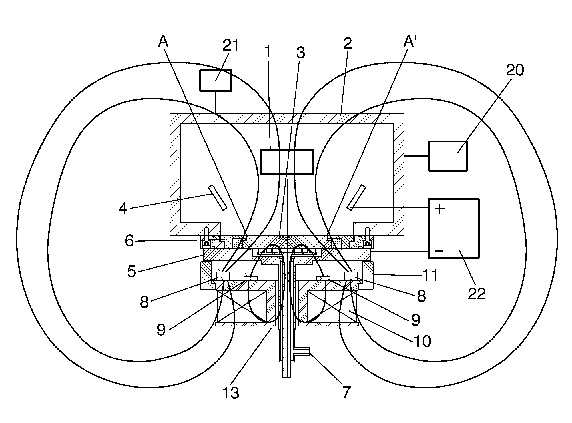
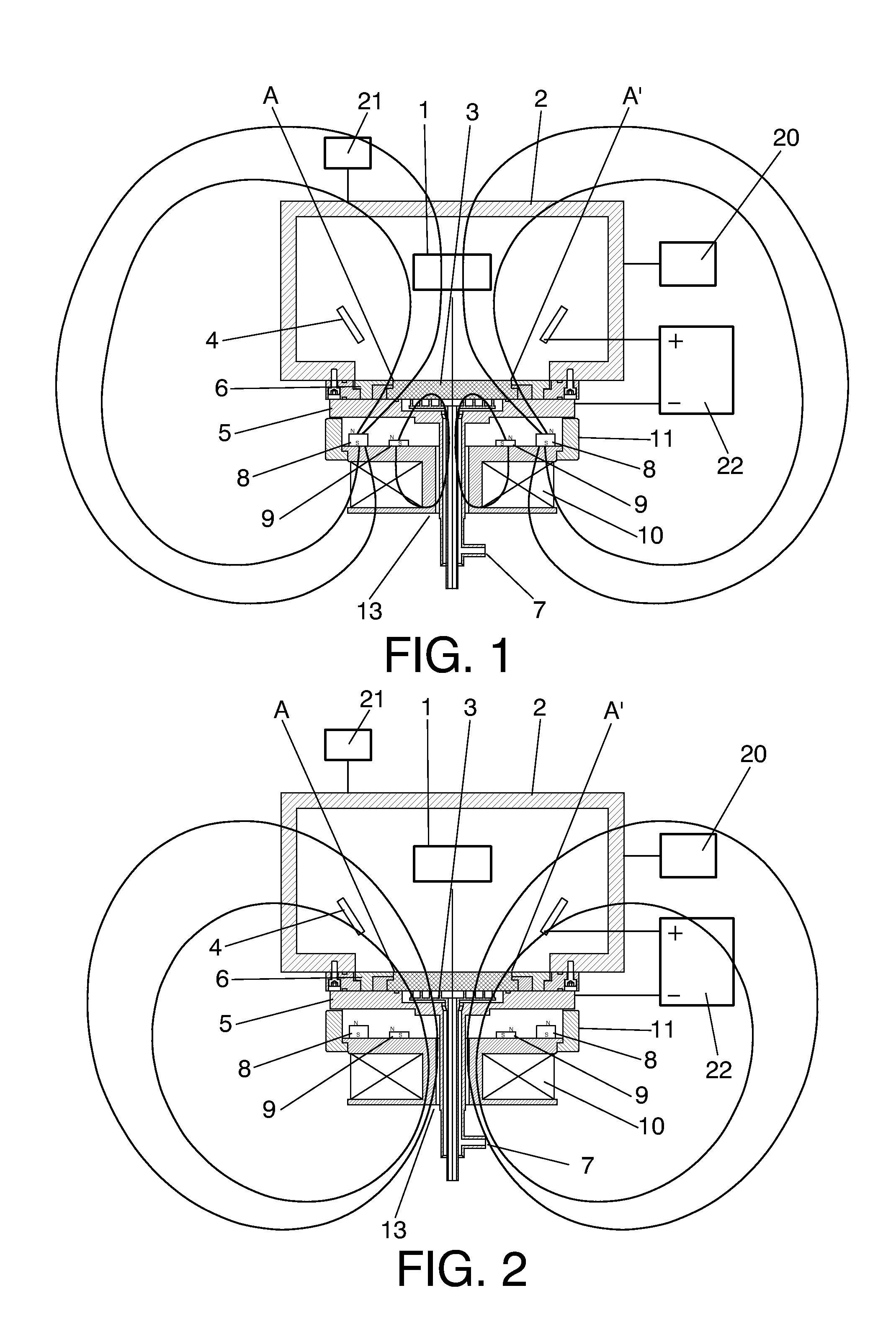
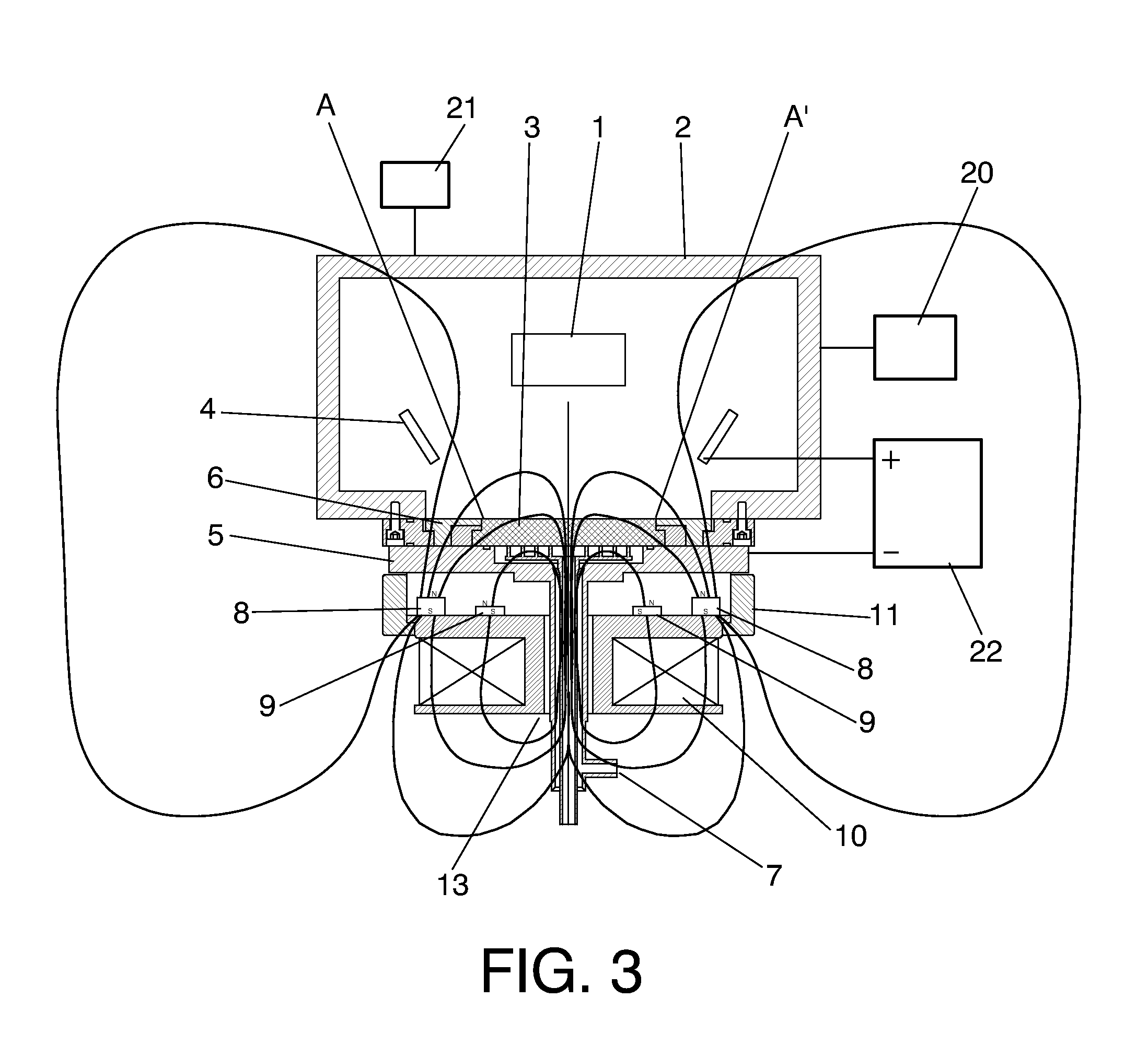
[0032]A first aspect of the invention relates to an arc evaporator, comprising:

[0033]at least one anode configured to be located in an evaporation chamber configured to house at least one object to be coated;

[0034]a cathode, the cathode comprising[0035]an inner surface configured to be located inside such evaporation chamber such that an arc between said at least one anode and the cathode can cause an evaporation of material in said inner surface, and[0036]an outer surface configured to not be located inside the evaporation chamber; and

[0037]a system for generating a magnetic field configured to generate a magnetic field in the evaporation chamber.

[0038]According to the invention, the system for generating a magnetic field comprises:[0039]a first subsystem consisting of a set of permanent magnets (the set of permanent magnets consists of one or more permanent magnets) configured to be located outside the evaporation chamber and such that said set of permanent magnets produces a firs...


PUM

PropertyMeasurementUnit
Magnetic fieldaaaaaaaaaa
Frequencyaaaaaaaaaa
Diameteraaaaaaaaaa

Abstract

The invention relates to an arc evaporator which comprises at least one anode (4), a cathode (3) and a system for generating a magnetic field comprising a first subsystem consisting of a set of permanent magnets (8, 9) which produces a converging magnetic field component and a second subsystem comprising at least one coil (10) and configured to operate in at least a first operating mode in which it generates a second diverging magnetic field component.

Description

TECHNICAL FIELD OF THE INVENTION[0001]The invention is comprised in the field of arc evaporators and, more specifically, in the field of arc evaporators including a magnetic steering system for the arc.BACKGROUND OF THE INVENTION[0002]Arc evaporators are systems or machines intended to evaporate an electrically conductive material, such that said material can move through a chamber (in which a state of vacuum or of very low pressure is normally established) to be deposited on a surface of a part to be coated with the material. In other words, machines of this type are used for coating parts and surfaces.[0003]Arc evaporator machines usually comprise, in addition to the chamber itself, at least one anode and at least one cathode, between which an electric arc is established. This arc (which in a typical case can represent a current of 80 A and be applied under a voltage of 22 V) impinges on a point of the cathode (known as cathode spot) and generates, in correspondence with said poin...

Claims


Application Information

Patent Timeline
IPC IPC(8): C23C14/32
CPCC23C14/325H01J37/3266H01J37/32055
Inventor GOIKOETXEA LARRINAGA, JOSURUIZ DE GOPEGUI LLONA, UNAIGARMENDIA OTAEGI, KEPADELGADO CASTRILLO, ANDONI
Owner FUNDACION TEKNIKER
Why Eureka
Try Eureka