Apparatus for monitoring at least one thermal control device, and associated control unit and control system

a technology for controlling devices and control systems, applied in the direction of heating types, space heating and ventilation details, domestic heating details, etc., can solve the problems of not being optimal, and not allowing the control of a decentralized heating system. , to achieve the effect of reducing the energy consumption of heating devices

Inactive Publication Date: 2017-09-07
BETTER WATT
View PDF3 Cites 5 Cited by
  • Summary
  • Abstract
  • Description
  • Claims
  • Application Information

AI Technical Summary

Benefits of technology

[0005]These related solutions include control apparatuses comprising a central thermostat connected to a remote server via a communication network. The thermostat is equipped with a temperature sensor and a memory for the storage of a software application. Conventionally, the thermostat is designed to switch the heating devices in a central heating system between a “comfort” mode and an “economy” mode, or for the control thereof in relation to a plurality of setpoint temperatures, within time intervals which are predefined by a user. The thermostat is also designed, by means of the temperature sensor, for the regulation of the heating temperature in relation to a predefined setpoint temperature. A user can then connect to the network which communicates with the thermostat using a mobile communication device and, by means of the remote server, can select the setpoint temperature to be set on the thermostat. Finally, by means of its software application, a thermostat of this type is capable of learning the habits of the user, in terms of temperature settings, thereby permitting the regular optimization of heating time intervals and heating times in respect of desired temperature levels, in order to reduce the energy consumption of heating devices.
[0007]Other systems for the reduction of the energy consumption of thermal control devices are proposed by operators, involving the deployment of the consumption cut-off principle. More specifically, systems of this type comprise an electronic console arranged within the residence. The electronic console is connected firstly to a communication network which is external to the residence, and secondly to the electric power supply system of the thermal control devices. Accordingly, the operator of the energy cut-off service can, by means of the communication network and the electronic console, momentarily interrupt the electric power supply to a number of high-consuming heating devices, for example in order to prevent peaks in energy consumption, or to permit the client of the service to enjoy the optimum exploitation of reduced tariff time intervals.
[0011]The invention described hereinafter is intended to rectify all or part of the disadvantages of the prior art, specifically by the disclosure of an apparatus for the monitoring of at least one thermal control device for the purposes of the further reduction of the energy consumption of the, or of each thermal control device, whilst simultaneously permitting the control of centralized and decentralized thermal control systems, without impairing the ultimate thermal comfort of the user.
[0017]The energy consumption setpoint corresponds to an energy quota which is allocated to the control device over a given period of time. As the control instructions for each thermal control device include at least one temperature setpoint and one energy consumption setpoint, the or each control device permits the delivery of the electric power supply to the associated thermal control device, in an endeavor to achieve the setpoint temperature, for such time as the allotted energy consumption quota is not exceeded. The thermal comfort of the user is thus regulated on a continuous basis as a function of energy consumption, and comfort time settings are accurately adjusted to the strict degree necessary. This permits the minimization of overall energy consumption, without impairing the ultimate thermal comfort of the user. Moreover, as a result of the connection of each control device to the electric power supply of the associated device, the control apparatus according to the invention is advantageously compatible with all existing technologies employed in thermal control devices. Conversely, monitoring systems from the prior art employ a standard wired system for the control devices, thus rendering them specific to particular technologies. Advantageously, the control apparatus according to the invention permits the control of both centralized and decentralized systems.
[0018]Moreover, the presence of at least one measuring element for a variable which is representative of energy consumption within the control apparatus advantageously permits the improvement of the accuracy of the calculation of temperature and energy consumption setpoints.

Problems solved by technology

However, a control apparatus of this type does not permit the control of a decentralized heating system comprised, for example, of a series of radiators in a residential building.
Another disadvantage is that the reduction in the energy consumption of heating devices is not known and, in consequence, is not optimal.
This results in problems in the control of heating within the residence, such as rooms which are excessively hot or excessively cold for the residents.
A disadvantage of systems of this type is their inability to regulate heating in relation to a setpoint temperature.
However, the reduction in the energy consumption of heating devices achieved by a control module of this type is not known and, in consequence, is not optimal, specifically on the grounds that this reduction is executed from the viewpoint of the service operator.
Moreover, a control method deployed using a control module of this type, whilst intended to ensure an acceptable level of comfort within the residence can, by very dint of the energy cut-off principle, result in situations in which the ultimate thermal comfort of the user is compromised.

Method used


Image

  • Apparatus for monitoring at least one thermal control device, and associated control unit and control system
  • Apparatus for monitoring at least one thermal control device, and associated control unit and control system
  • Apparatus for monitoring at least one thermal control device, and associated control unit and control system

Examples


Embodiment Construction

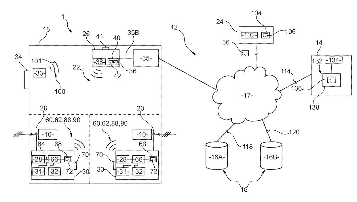
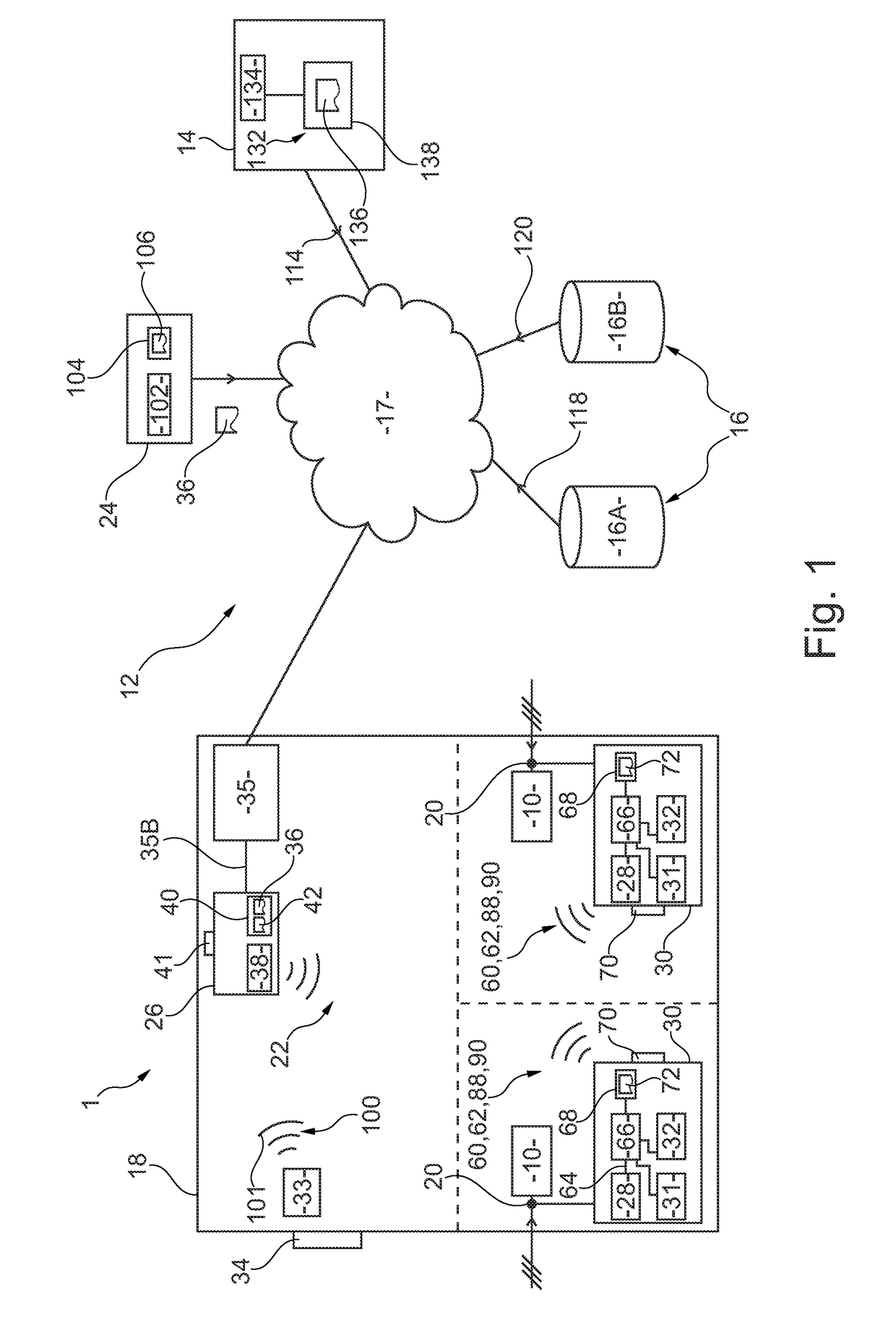
[0043]In the description hereinafter, the term “thermal control device” is to be understood as any device which is capable of acting on the temperature of a location, a room in a building or a facility, either by means of a heating mode or a cooling mode. Such a device may be dedicated to one of these modes, for example a boiler or a radiator for a heating mode or an air-conditioning system for a cooling mode, or may be capable of operating in either of these two modes, as in the case of a reversible heat pump, for example.

[0044]The term “computer” is likewise to be understood as any electronic device equipped with means for the calculation of data and means for the storage of data including, for example, a desktop computer, a portable computer, a wireless communication device such as a smartphone, or a digital tablet computer, whereby the above list is not exhaustive.

[0045]The “time scheduling” of a zone is moreover to be understood as a list of time slots staggered over a predeter...


PUM


Abstract

Some embodiments are directed to an apparatus for monitoring at least one thermal control device, the device including a power supply input terminal suitable for being connected to an electric power source. The monitoring apparatus includes an electronic console that stores control instructions from the or each thermal control device. The control instructions include, for each thermal control device, at least one temperature setpoint and one energy consumption setpoint; at least one temperature sensor suitable for providing temperature data measurements, the temperature and energy consumption setpoints being determined based on parameters comprising at least said temperature data measurements; and at least one device for controlling the electric power supply of the or one of the thermal control devices, connected to the power supply input terminal of said device and suitable for controlling the electric power supply of the device based on at least the temperature and energy consumption setpoints.

Description

CROSS REFERENCE TO RELATED APPLICATION[0001]This application is a National Phase filing under 35 C.F.R. §371 of and claims priority to PCT Patent Application No.: PCT / FR2015 / 05223, filed on Aug. 18, 2015, which claims the priority benefit under 35 U.S.C. §119 of French Application No.: 1458744, filed on Sep. 16, 2014, the contents of which are hereby incorporated in their entireties by reference.TECHNICAL FIELD[0002]Some embodiments relate to an apparatus for the monitoring of at least one thermal control device in the interests of reducing its energy consumption, and to an associated control unit and control system. Some embodiments specifically relate to the optimized control of devices for the heating or management of hot water in residential buildings.RELATED ART[0003]The energy consumption of devices for the heating and management of hot water accounts, on average, for over 60% of the total energy consumption of a residential building.[0004]In order to reduce the energy consump...

Claims


Application Information

Patent Timeline
Patent Type & Authority Applications(United States)
IPC IPC(8): F24D19/10G05B19/048F24D13/00G05D23/19F24D3/02
CPCF24D19/1081G05D23/1917G05D23/1932G05B2219/2658F24D13/00G05B19/048F24D3/02G05D23/1905F24D19/1006
Inventor GHANEM, GEORGES
Owner BETTER WATT
Why Eureka
Try Eureka