Acoustic device for ultrasonic imaging

a technology of ultrasonic imaging and acoustic device, which is applied in the field of ultrasonic imaging acoustic device, can solve the problems of inherently limited effective viewing angle, large size of the transducer, and generation of undesired signals or reverb, and achieve the effect of reducing, alleviating or eliminating on

Inactive Publication Date: 2012-01-26
KONINKLIJKE PHILIPS ELECTRONICS NV
View PDF3 Cites 4 Cited by
  • Summary
  • Abstract
  • Description
  • Claims
  • Application Information

AI Technical Summary

Benefits of technology

[0009]Accordingly, the invention preferably seeks to mitigate, alleviate or eliminate one or more of the above mentioned disadvantages singly or in any combination. In particular, it may be seen as an object of the present invention to provide an acoustic device that solves the above mentioned problems of the prior art with the limited viewing angle in ultrasonic imaging.

Problems solved by technology

Generally, the transducers used in external applications (e.g. imaging of organs from outside of the body) are based on phased array configuration, however for internal use within the body (e.g. catheter applications), the size of the transducer is very limited.
One of the fundamental problems for imaging through a liquid / liquid interface is the reflection of the ultrasound from this interface backwards to the transducer, which generates undesired signals or reverberation in an ultrasound image.
Once a suitable liquid pair is chosen, the effective viewing angle, to be used for example in a B-scan imaging, is inherently limited by the fact the reflection, R, in the liquid / liquid interface is increasing relatively fast at angles different from normal incidence.
This can be compensated by tilting the acoustic lens formed by the liquid / liquid interface, but this disadvantageously limits the effective viewing angle of the imaging device because the tilting is in turn limited by the mechanical constraints in narrow catheter applications.
Thus, both the reflection at normal and non-normal incidence, and the effective viewing angle of the imaging device are to some extent constraining or hindering further improvements in this field.

Method used


Image

  • Acoustic device for ultrasonic imaging
  • Acoustic device for ultrasonic imaging
  • Acoustic device for ultrasonic imaging

Examples


Embodiment Construction

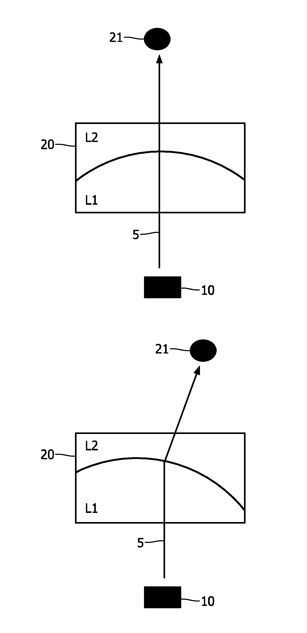
[0042]FIG. 1 shows two schematic drawings of refracting ultrasound the interface between two immiscible liquids. In both parts of the figure, the acoustic pulse 5 is emitted from the transducer 10 as also indicated by the arrows originating from the transducer and continued on the other side of the acoustic interface 7. On the side of the transducer 10, the first liquid L1 is positioned, the first liquid together with the second liquid L2 define the acoustic interface 7. The acoustic interface is typically formed due to immiscibility of the two liquids in an electrowetting lens, but the acoustic interface could also be defined by a membrane or similar separating the two liquids, or, more generally, the two fluids apart. It should be noted that the acoustic interface 7 is for illustrative purposes given as a straight interface, hence no focusing power is present. In typically applications, the interface will be curved or formed as a meniscus. The transducer 10 may be embedded in the ...


PUM


Abstract

The present invention relates to an acoustic device for ultrasonic imaging of an object (21). The device comprises an acoustic transducer (10 and an acoustic lens (20) arranged to variably refract the said acoustic pulse to and/or from the acoustic transducer. The acoustic lens comprising a first (L1) and a second fluid (L2) being separated by an acoustic interface (7), the normal of the said acoustic interface forming a relative angle of incidence (AI) with the said acoustic pulse, e.g. an electrowetting lens. The first and the second fluid of the acoustic lens (20) are specifically chosen so that the acoustic interface (7) has a reflection minima at a non-zero relative angle of incidence (AI). The invention is advantageous for obtaining an improved acoustic device having a substantially lower reflection in a broader interval of incidence angles as compared to hitherto seen ultrasonic imaging utilising acoustic lenses with two or more fluids as the active acoustic refracting entities.

Description

FIELD OF THE INVENTION[0001]The present invention relates to an acoustic device for ultrasonic imaging. The invention also relates to a catheter with an acoustic device, and to an imaging system with an acoustic device according to the present invention.BACKGROUND OF THE INVENTION[0002]Ultrasonic imaging is one of the most important diagnostic tools in healthcare technology. Generally, the transducers used in external applications (e.g. imaging of organs from outside of the body) are based on phased array configuration, however for internal use within the body (e.g. catheter applications), the size of the transducer is very limited. One of the solutions for catheter applications is the liquid lens ultrasound configuration, where the scanning of the ultrasound is performed by tilting a liquid / liquid interface in front of the transducer, which refracts the ultrasound, therefore allowing imaging within a well defined sector in front of the catheter, a so-called B-scan imaging. One exam...

Claims


Application Information

Patent Timeline
Patent Type & Authority Applications(United States)
IPC IPC(8): A61B8/12A61B8/13A61B8/00
CPCG10K11/30
Inventor DELADI, SZABOLCSSUIJVER, JAN FREDERIKMARESCA, DAVID
Owner KONINKLIJKE PHILIPS ELECTRONICS NV
Why Eureka
Try Eureka