Headrest and method for forming the same

a headrest and foaming technology, applied in the field of headrests, can solve the problems of affecting the appearance of the outer appearance of the headrest, requiring a number of parts and a long time involved, and causing objectionable creases or deformation spots, and prior-art headrest structure and foaming procedures have been found defective in terms of incomplete sealing

Inactive Publication Date: 2000-11-21
TACHI S CO LTD
View PDF8 Cites 38 Cited by
  • Summary
  • Abstract
  • Description
  • Claims
  • Application Information

AI Technical Summary

Problems solved by technology

Hence, there has been the necessity for a worker to close such opening by means of a particular closing element such as a fastener of Velcro or loop-and-hook fastening type, which renders troublesome the headrest assembling steps on the worker's part and requires a number of parts and lengthy period of time involved.
Further, such mere juxtaposition of the three separate layers with one another in this prior-art headrest gives a rise to the drawback that an external force given by a user to the headrest for its inclination purpose causes the top covering layer or trim cover assembly to dislocate from a given position relative to the foam padding layer, resulting in creation of objectionable creases or deformed spots on the outer aesthetic appearance of headrest.
However, even this prior-art headrest structure and foaming procedures have been found defective in terms of incomplete sealing because the flange portion and inner wall of foaming die are simply contacted with each other on a flat plane to retain therebetween the local part of covering member adjacent the elongated hole, which remains of a high likelihood that liquid base foaming material will be invaded or leaked therethrough.
Moreover, such arrangement and steps cause a difficulty in quickly locating the headrest frame at a given position within the foaming die in order to insure avoiding the leakage problem.

Method used


Image

  • Headrest and method for forming the same
  • Headrest and method for forming the same
  • Headrest and method for forming the same

Examples


Embodiment Construction

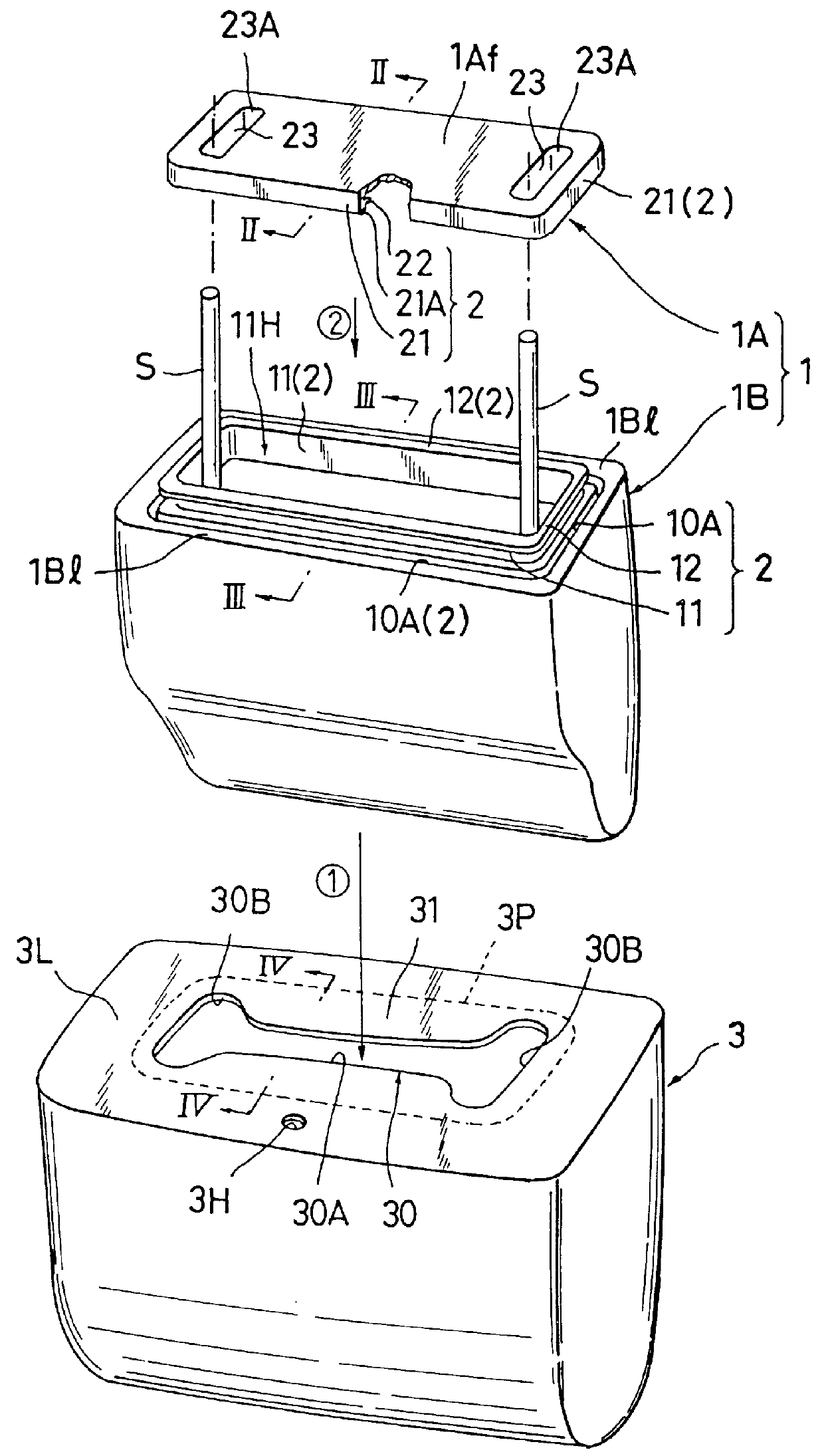
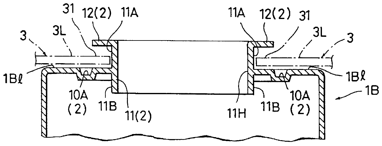
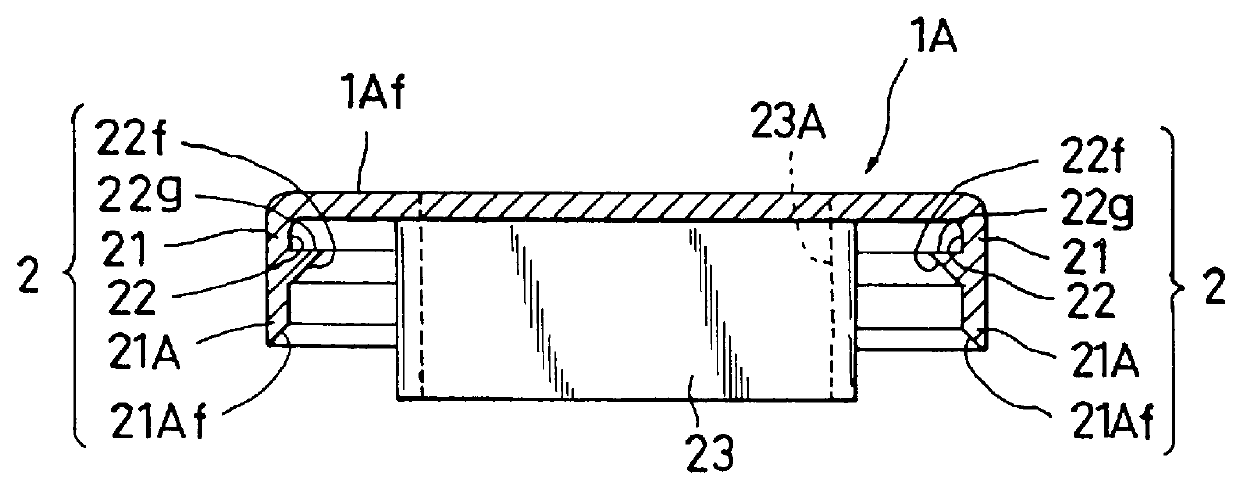
Referring to FIGS. 1 through 8, there are illustrated, by way of example, one preferred mode of a process for forming a headrest and one preferred mode of the resulting headrest formed thereby, in accordance with the present invention.

FIGS. 1 and 8 show an exemplary construction of headrest (HR) in accordance with the present invention, which is of the fore-and-aft inclinable type for use on the seat back (SB) of automotive seat. This kind of headrest has, incorporated therein, a known ratchet inclination mechanism, generally designated by (M) in FIG. 5, by means of which the headrest body may be adjustably inclined in the fore-and-aft direction with respect to the two headrest stays (S) or the seat back (SB), so that a passenger on a rear seat can incline the headrest body in the direction forwardly of the seat back (SB) to attain a wide view in the forward direction of an automobile or vehicle.

In accordance with the present invention, a sealing enclosure means (1) is provided to c...


PUM


Abstract

A headrest of the type inclinable fore-and-aft with respect to a headrest stay upon a seat, which includes a trim cover assembly having an opening formed at one side thereof, and includes an inclination mechanism connected to the headrest stay within the trim cover assembly. In forming the headrest, an inner sealing enclosure element is provided in the interior of trim cover assembly to accommodate those inclination mechanism and headrest stay therein, with a free part of the headrest stay projecting outwardly through a hole of the inner sealing enclosure element, while one the other hand, an outer sealing element is securely engaged with that inner sealing enclosure element so as to close both opening of the trim cover assembly and hole of the inner sealing enclosure element. This closing and sealing effect is made positive by a particular male and female sealing engagement arrangement defined between the inner sealing enclosure element and outer sealing element. A method for executing such process is provided to attain a sealed structure of headrest which prevents a liquid base foaming material against leakage therefrom during a foaming step.

Description

BACKGROUND OF INVENTION1. Field of the InventionThe present invention relates to a headrest for use on an automotive seat and a method for forming the same. More particularly, the invention is directed to a headrest of the fore-and-aft inclinable type having an inclining mechanism incorporated therein, wherein the headrest can be inclined forwardly and backwardly of the seat via the inclining mechanism, and also directed to a method for forming that particular type of headrest under a foaming process comprising the steps of injecting a liquid base foaming material into the hollow interior of a trim cover assembly of a predetermined headrest shape, in which the inclining mechanism and a headrest frame with headrest stays have been installed, and curing the injected liquid base foaming material to create and fill a foam padding in the trim cover assembly, integrally together with the inclining mechanism and headrest frame.2. Description of Prior ArtAmong various sorts of headrest for ...

Claims


Application Information

Patent Timeline
Patent Type & Authority Patents(United States)
IPC IPC(8): B60N2/48B60N2/70
CPCB60N2/4847B60N2/70Y10S297/01B60N2/847
Inventor TAKEI, YOSHIYUKITORIUMI, TAKAYUKI
Owner TACHI S CO LTD
Why Eureka
Try Eureka