Synthesis of overlapping chirp waveforms

a chirp waveform and chirp waveform technology, applied in the field of digital radar landmass simulators, can solve the problems of extreme difficulty in simulation and testing equipment, inability to simulate this continuum, and inability to effectively simulate land mass simulation using a semi-

Inactive Publication Date: 2000-11-21
AIRPORTS AUTHORITY OF INDIA
View PDF11 Cites 38 Cited by
  • Summary
  • Abstract
  • Description
  • Claims
  • Application Information

AI Technical Summary

Problems solved by technology

It creates extreme difficulty for simulation and test equipment, however, since the return from multiple discrete targets overlap in time.
The problem faced in adapting digital radar landmass simulators (DRLMSs) to pulse compression radars is that the land mass simulation effectively requires a semi-infinite continuum of closely spaced targets.
It is not practical to simulate this continuum by processing the expanded waveforms; there are simply too many time-overlapping signals to create.
SAW waveform expansion / compression filters are very expensive, however, and each compression mode of each radar is likely to have a different SAW.
In order to cover a wide variety of target radars, the existing technology requires an expensive proliferation of dedicated hardware.

Method used


Image

  • Synthesis of overlapping chirp waveforms
  • Synthesis of overlapping chirp waveforms
  • Synthesis of overlapping chirp waveforms

Examples


Embodiment Construction

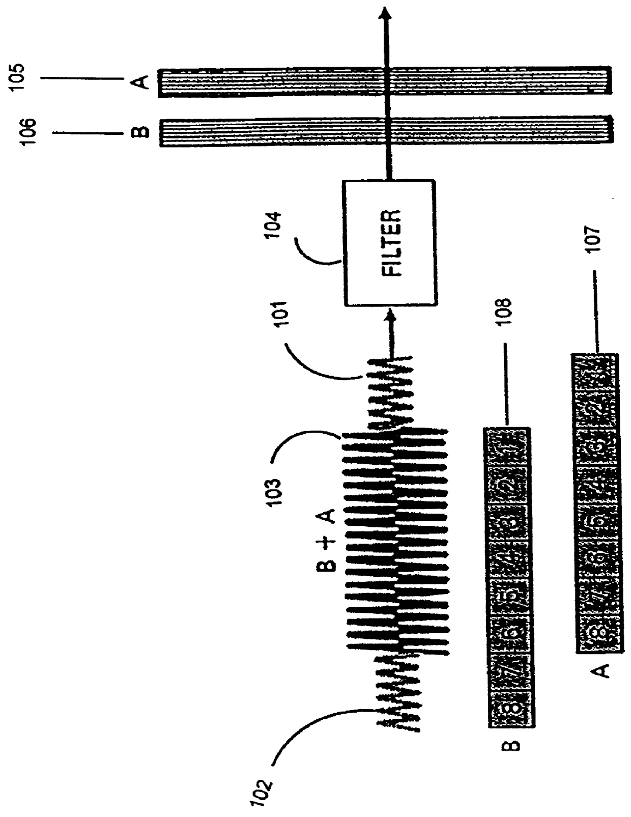
The problem is best illustrated by FIG. 1 which shows only two overlapping signals (signal A denoted in its analog form by 101 and in its digital form by 107 and signal B denoted in its analog form by 102 and its digital form by 108. The radar uses bandpass filters 104 to separate the signals 105 and 106. The problem for a stimulation / simulation tool is to generate the merged echoes 103. The problem is not the simple case of two echoes as illustrated in FIG. 1 but rather the echoes from a semi-infinite continuum of closely spaced target echoes.

Chirp / Doppler IF Generator Signal Generation (Chirp and Doppler)

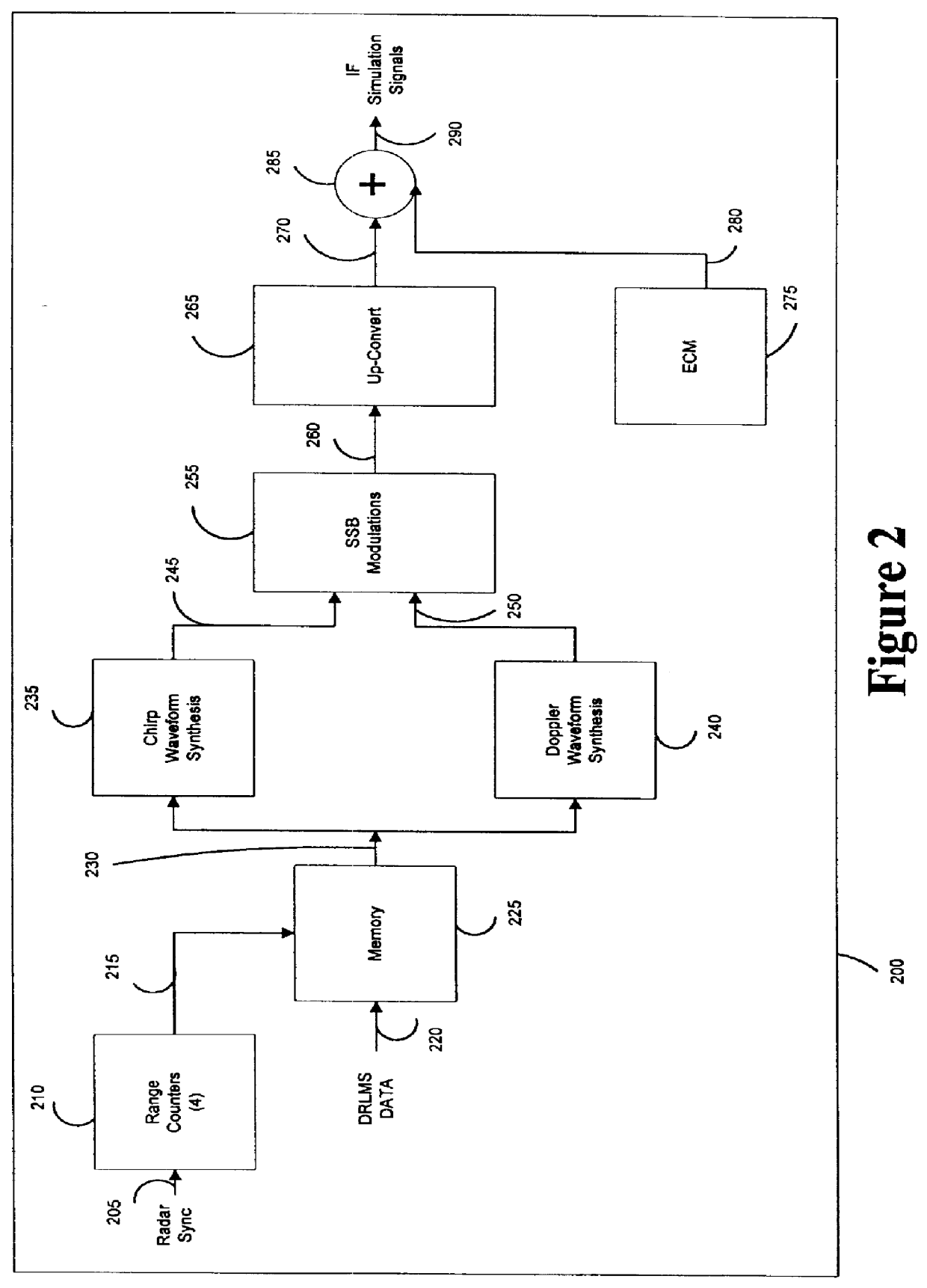
FIG. 2 is a simplified functional flow of the overlapping chirp / Doppler waveform synthesis process 200.

The radar sync signal 205 is supplied to the range counter unit 210 which generates the range counts 215 which are stored in the memory unit 225 and processed with the DRLMS data 220 to yield four signal strength values that have been time multiplexed together 230. This value 230...


PUM


Abstract

A digital radar landmass simulator (DRLMS) used for stimulation testing pulse radars, wherein the DRLMS operates by synthesizing time-overlapping chirp waveforms using finite impulse response filters. The DRLMS, thus, effectively generates many overlapping complex pulse signals from many radar reflectors representing a semi-infinite continuum of closely spaced targets. The DRLMS also allows the insertion/injection of the effects of Doppler shift and jamming into the synthesized modulated signal.

Description

1. Field of the InventionThe present invention relates generally to digital radar landmass simulators and, more particularly, to a system and method for synthesizing overlapping chirp waveforms for digital radar landmass simulators.2. Statement of the Prior ArtModern pulse compression radars utilize surface acoustic wave (SAW) filter technology in their exciter / receiver least replaceable units (LRUs) to generate expanded pulse waveforms for transmission. The same or similar SAW filters are then used to compress the received return pulses. This technology enables the radar to substantially improve its signal to noise ratio without sacrificing range resolution. It creates extreme difficulty for simulation and test equipment, however, since the return from multiple discrete targets overlap in time.The coincident timing of radar returns implies that the simulation equipment must be capable of generating multiple, individually phased waveforms in order to simulate closely spaced targets....

Claims


Application Information

Patent Timeline
Patent Type & Authority Patents(United States)
IPC IPC(8): G01S7/40G09B9/54G01S13/28
CPCG01S7/4052G09B9/54G01S2007/4095G01S7/4095
Inventor COOLEY, JAMES R.
Owner AIRPORTS AUTHORITY OF INDIA
Why Eureka
Try Eureka