Bucket assembly with an improved lip

a technology of shroud and shroud, which is applied in the direction of mechanical machines/dredgers, soil shifting machines/dredgers, construction, etc., can solve the problems of cracking within the lip, prolonging the useable life of the shroud, and requiring occasional replacement of the shroud

Inactive Publication Date: 2000-11-28
BIERWITH ROBERT S
View PDF12 Cites 75 Cited by
  • Summary
  • Abstract
  • Description
  • Claims
  • Application Information

AI Technical Summary

Benefits of technology

In accordance with a further aspect of the present invention, each connection pin further includes an oil-ring groove with an O-ring mounted therein to inhibit foreign matter from entering the shear groove.
Accordingly, an excavation bucket assembly in accordance with the present invention allows for shrouds to be connected to the lip of the bucket via slots that produce much lower stress concentration within the lip. Additionally, tooth assemblies for connection to the bucket assembly are constructed utilizing improved connecting pins that allow for a more reliable connection between the tooth and the nose portion, as well as allowing for easy replacement of the tooth portion.

Problems solved by technology

As a result, only the attachments normally need replacement when the front of the bucket becomes worn, thus prolonging the useable life of the larger and more expensive lip and side walls.
Likewise, the shroud is a part that is subject to wear and therefore occasionally needs replacement.
Therefore, the slot can lead to cracking within the lip.

Method used


Image

  • Bucket assembly with an improved lip
  • Bucket assembly with an improved lip
  • Bucket assembly with an improved lip

Examples


Embodiment Construction

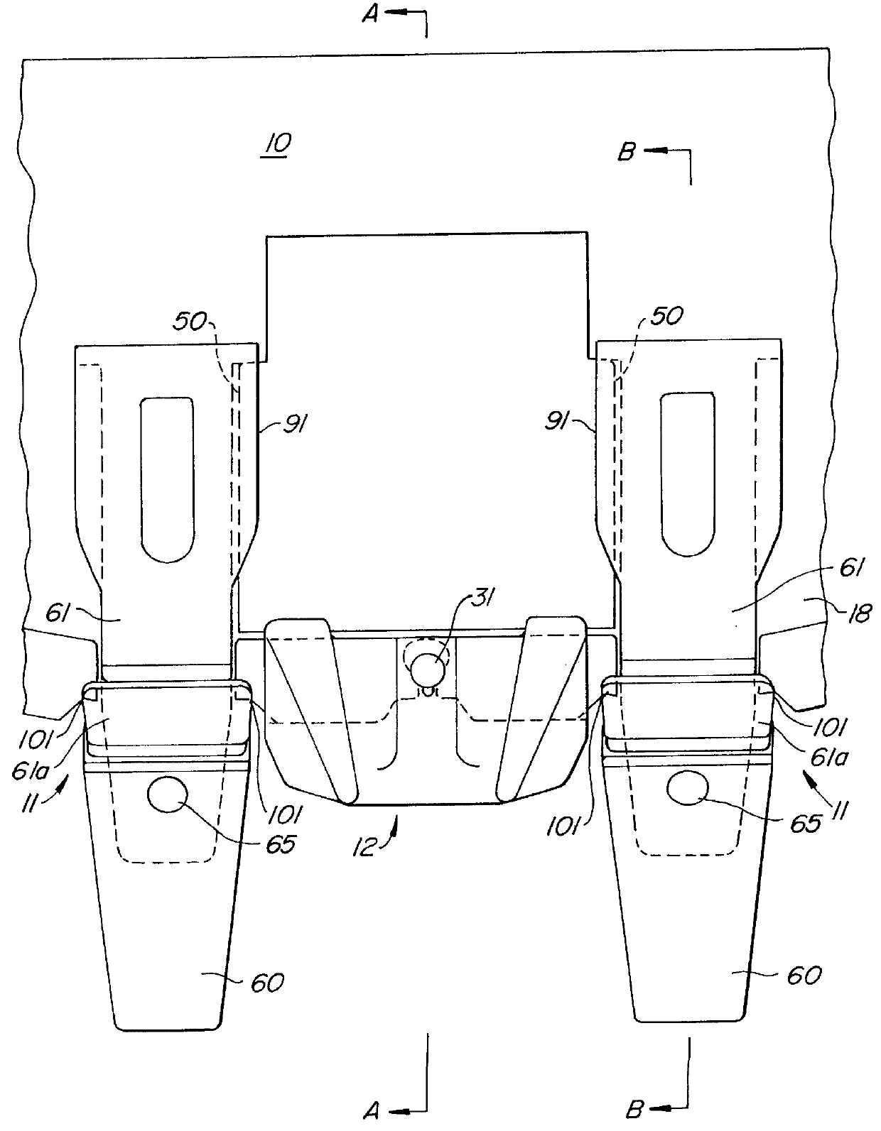
Referring to the figures, and more particularly to FIG. 1, a portion of an excavation bucket assembly comprises a bucket body 10, a plurality of tooth assemblies 11 connected to the bucket body, and a plurality of shrouds 12 interspersed between the tooth assemblies and also connected to the bucket body. Along a front portion of bucket body 10 is a lip 18 that runs longitudinally along the bottom wall of the bucket body and over which the tooth assemblies and shrouds are connected.

As best seen in FIG. 2, lip 18 has a plurality of key-holes 20 defined therein. Each key-hole 20 is defined by overlapping apertures 21, 22. In the preferred embodiment, aperture 21 is a substantially circular portion, while aperture 22 is a substantially elliptical portion. The elliptical portion is located proximally with respect to the bucket body, while the circular portion is located distally with respect to the bucket body. As can be seen in FIG. 2A, each key-hole 20 is defined along the lip with a s...


PUM


Abstract

An excavation bucket assembly for an excavation apparatus such as a front-end loader includes a plurality of shrouds and tooth assemblies mounted along a lip of the bucket body. The shrouds are connected via reusable connection pins that are biased within aligned connection-holes with a plunger assembly mounted within the connection pin. The connection-holes are defined by two overlapping ovals, with the proximal oval having a larger radius as compared to the distal oval. Additionally, an improved attachment pin is utilized to connect a tooth portion to a tooth body portion of the tooth assemblies that provides for a secure and reliable attachment and easy exchange of worn tooth portions.

Description

1. Field of the InventionThis invention relates to buckets for excavation vehicles such as front-end loaders and, more particularly, to teeth and shrouds utilized with such buckets and the manner in which they are connected along a front lip of such a bucket.2. Description of the Prior ArtExcavating buckets are used extensively in the construction and mining industries. The buckets are used with a variety of different excavating apparatus, such as backhoes, power shovels, front-end loaders, dragline equipment, etc. Although these buckets have many differences, they are generally formed with a rear wall, side walls, and a bottom wall. The walls cooperatively define an open front and a cavity for gathering earthen material and moving it to a dump site. The bottom edge of the open front is defined by a forward lip of the bottom wall. The lip is intended to engage the ground for collection of the material into the bucket cavity. The lip may be formed to have a linear or arcuate-shaped e...

Claims


Application Information

Patent Timeline
Patent Type & Authority Patents(United States)
IPC IPC(8): E02F9/28
CPCE02F9/2825E02F9/2883E02F9/2841
Inventor BIERWITH, ROBERT S.
Owner BIERWITH ROBERT S
Why Eureka
Try Eureka