Short point anti-cross-threading design

a technology of anti-cross-threading and short points, applied in the direction of screw threads, screw threads, screw-thread articles, etc., can solve the problems of severe affecting productivity, and inability to meet the requirements of assembly, so as to resist cross-threading upon engagement and facilitate engagement

Inactive Publication Date: 2000-12-05
TEXTRON IPMP +1
View PDF24 Cites 28 Cited by
  • Summary
  • Abstract
  • Description
  • Claims
  • Application Information

AI Technical Summary

Benefits of technology

A general object of the present invention is to provide a fastener member, stud or other threaded member, having a novel point on an end thereof which promotes alignment between the fastener member and a threaded bore, facilitates engagement of the fastener member in a threaded bore of a correspondingly threaded female member and resists cross-threading upon engagement, especially in applications involving blind holes or the use of very thin threaded holes.
An object of the present invention is to provide a fastener member which is capable of rapid engagement with a tapped bore so as to reduce the assembly installation time and to improve the ergonomics of a typical installation of a fastener member with a tapped bore, and also which provides improved performance when used with an automated assembly process or equipment.
Yet another object of the present invention is to provide a fastener member having a novel point which length is minimized so as to lower material cost, reduce the weight of the fastener member and minimize interference problems with the point of the fastener member with other components.
A further object of the present invention is to provide a fastener member which lowers manufacturing cost as the fastener member threads and the point are roll threaded in one pass.
To engage the fastener member with the female member, the point is inserted into the threaded bore in the female member. Rotational movement and an end load are applied to one of the fastener member or the female member to first attain alignment and then engage the threads on the transition portion with the threads in the threaded bore in the female member; thus once proper alignment has been achieved, engagement of the threads on the shank portion is achieved. The unthreaded radiused portion of the point will engage the crests of the internal thread and will allow and promote a pivoting movement of the fastener member, so that the fastener axis and the axis of the internally threaded bore are moved into general alignment. The truncated nature of the threads on the transition portion serve to promote ans assist in attaining alignment. These truncated threads can move past the internal or female threads without engagement that would hamper movement of the fastener member to an aligned position. The truncated nature of the threads also promotes threaded engagement with the internal threads. Engagement of the threads on the transition portion complete the alignment of the fastener member with the female member. As such, co-alignment of the fastener member and the internally threaded bore is attained prior to the engagement of the threads on the shank portion with the internal thread, thus promoting proper engagement and avoiding a cross-thread condition.

Problems solved by technology

Cross-threading is an unacceptable condition.
Cross-threading is a common occurrence in prior art fastener members, and extremely troublesome in automated assembly operations.
In an automated assembly situation, the occurrence of cross-threading can severely affect productivity.
Many of the existing machine screw applications cannot tolerate additional point length due to interference in blind tapped holes or other mating components because most applications are replacing standard machine screws.
Applicant has found, however, that in some applications, such as blind holes, the point length of the fastener member disclosed in Ser. No. 08 / 916,164 is too long making it unsuitable for use in this applications.
In addition, in the applications which involve the use of very thin threaded holes, such as in "Tinnerman" type push-on clips, the fastener member disclosed Ser. No. 08 / 916,164, which uses a long, bulbous point to align itself, is not suitable for use in these applications.

Method used


Image

  • Short point anti-cross-threading design
  • Short point anti-cross-threading design
  • Short point anti-cross-threading design

Examples


first embodiment

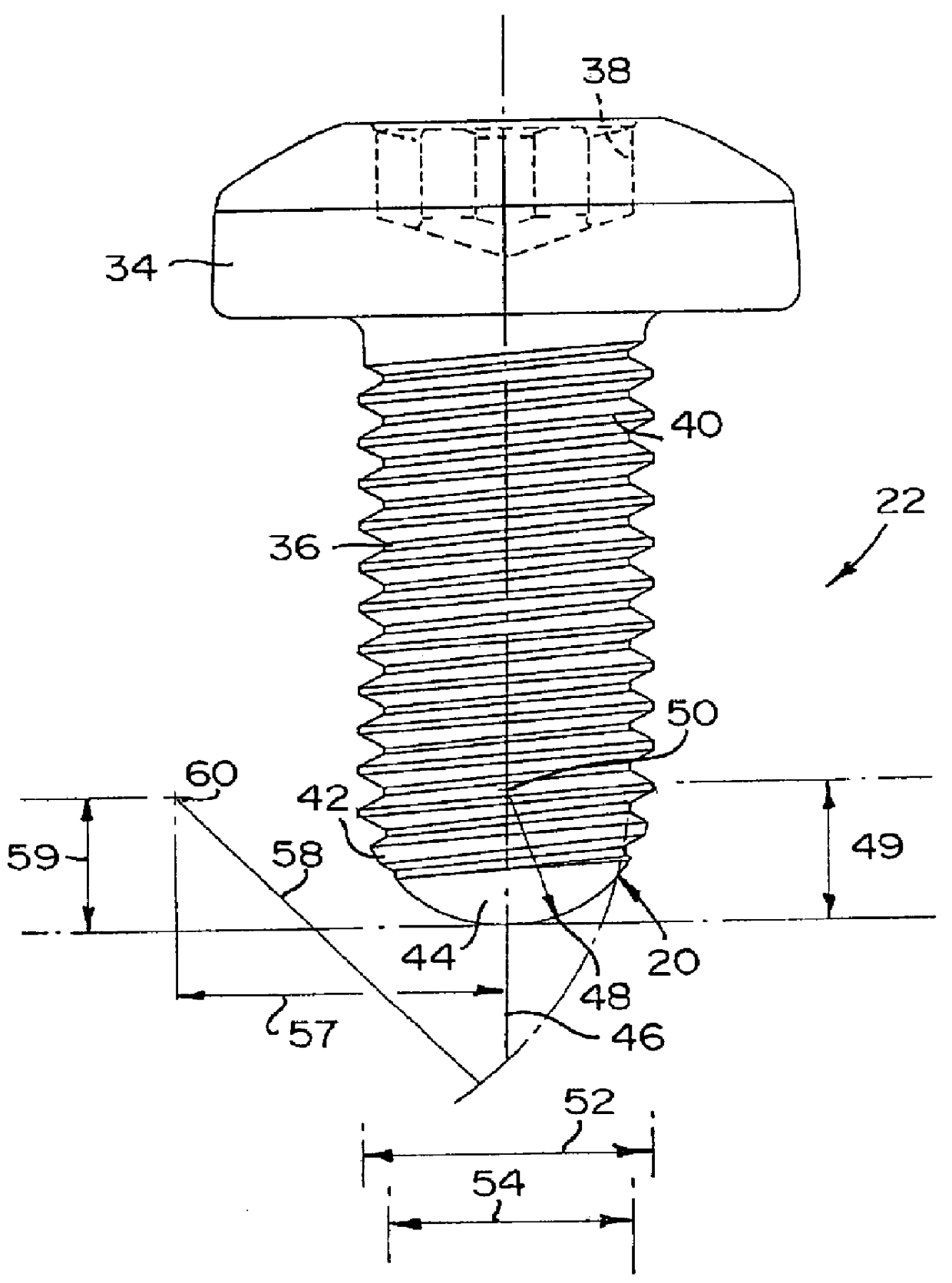
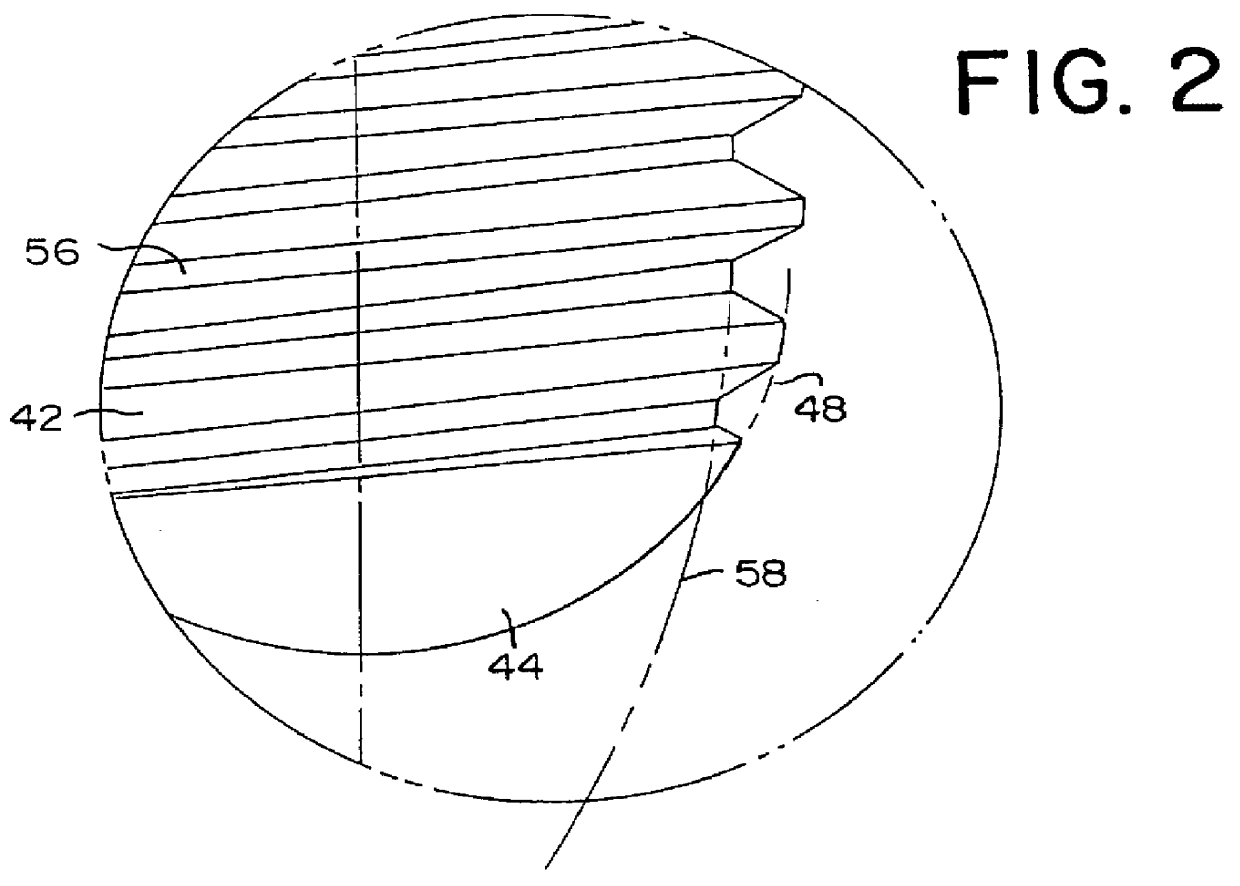
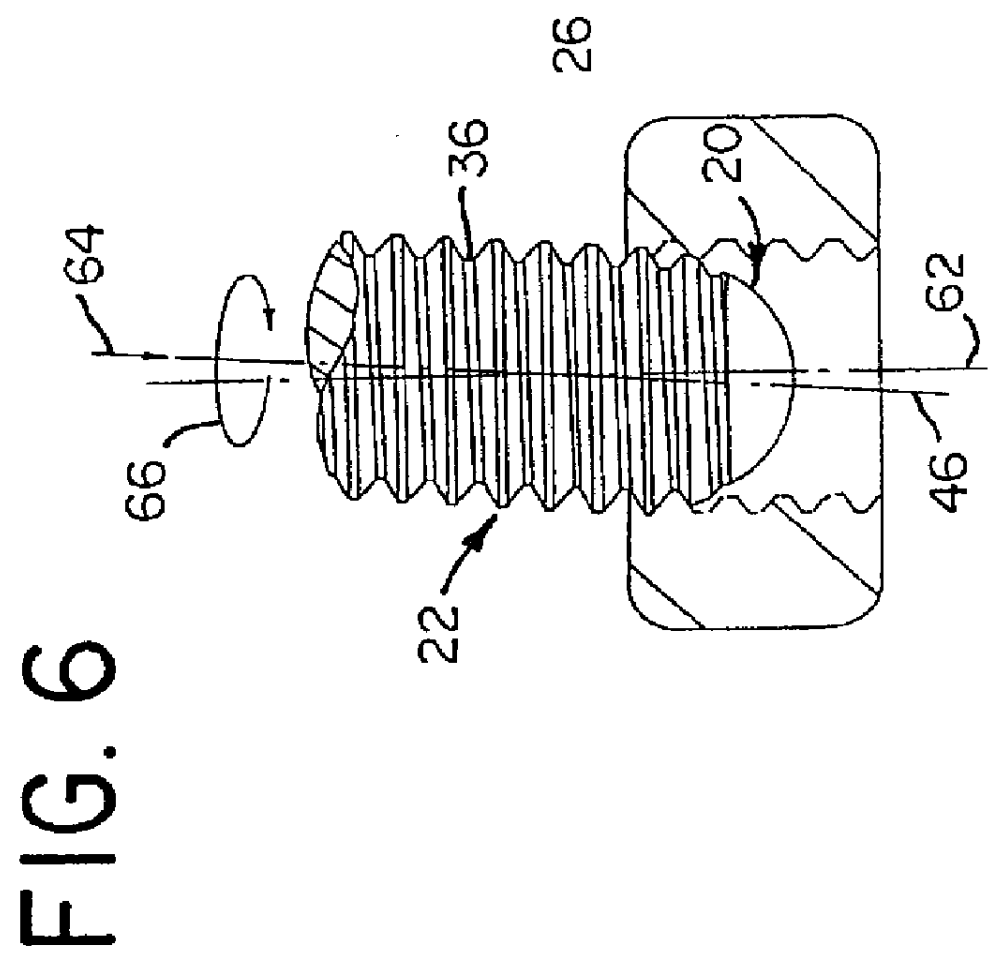
the novel point 20 on the fastener member 22 is shown in FIGS. 1 and 2. A second embodiment of the novel point 20b on the fastener member 22b is shown in FIGS. 8 and 9. Like elements in each embodiment are denoted with like reference numerals with the second embodiment having the suffix "b" after the reference numeral.

The generalities of each fastener member 22, 22b is described with respect to the first embodiment of the fastener member 22. Generally, the fastener member 22 of the present invention has a head 34 with a threaded shank portion 36 extending therefrom and the novel point 20 at the end of the threaded shank portion 36. A multilobular drive recess 38, preferably a TORX PLUS.RTM. recess, is provided in the head 30. The threaded shank portion 36 has a plurality of machine screw helical threads 40 thereon. The novel point 20 is provided on the opposite end of the threaded shank portion 36 from the head 34 and includes a threaded transition portion 42 extending from the end ...


PUM


Abstract

The present invention provides a novel fastener member, stud, or other threaded member, for engagement with a female member, and the method of assembly thereof. The fastener member has a novel point which facilitates engagement of the fastener member in the threaded bore, greatly reduces the possibility of cross-threading and is especially suited for use in applications involving blind holes or the use of very thin threaded holes. The fastener member has a threaded shank portion. A point is provided at the end of the shank portion and includes an unthreaded radiused portion and a threaded transition portion between the shank portion and the radiused portion. The major diameters of the threads of the transition portion gradually lessen between the opposite ends thereof. The minor diameters of the threads of the transition portion gradually lessen between the opposite ends thereof. The radiused portion can be provided with a truncated end surface.

Description

This invention is generally directed to a threaded male fastener member, or other threaded member, having a novel point which facilitates engagement of the fastener member in a threaded bore of a correspondingly threaded female member and prevents the member from cross-threading upon engagement, and the method of assembly thereof. Either the member or the female member may be driven, the other member being stationary during the assembly.During automated or manual assembly of an externally threaded fastener member with an internally threaded member, such as a nut, a tapped bore in a workpiece, or an internally threaded rivet staked to a workpiece, cross-threading can occur at assembly. Cross-threading is an unacceptable condition.To obtain proper alignment and engagement, the external thread on the fastener member engages with the internal thread in the female member and the external thread then follows the helix path of the internal thread. The mating of the helix angle of the inter...

Claims


Application Information

Patent Timeline
Patent Type & Authority Patents(United States)
IPC IPC(8): B21H3/06B21H3/00F16B35/04
CPCF16B35/047B21H3/06
Inventor DONOVAN, STEVEN P.
Owner TEXTRON IPMP
Why Eureka
Try Eureka