Chamber for reception, lateral division and redirection of liquid metal flow

a technology of liquid metal flow and chamber, which is applied in the direction of liquid transferring devices, manufacturing converters, furnaces, etc., can solve the problems of slag to be re-entrained, disturb the smooth flow required to properly, and many problems

Inactive Publication Date: 2000-12-05
PSC TECH
View PDF13 Cites 17 Cited by
  • Summary
  • Abstract
  • Description
  • Claims
  • Application Information

AI Technical Summary

Benefits of technology

It is a further object to provide such an impact pad to eliminate problems associated with slag emulsification, flow stagnation regions, thermal inhomogeneity, short-circuit flow, liquid residence distribution, and in particular, initial splash when the ladle is first opened.
It is still a further object to provide such an impact pad that is easy to use and manufacture.

Problems solved by technology

The aforementioned flow patterns result in many problems.
1. Non-separation of slag and inclusion particles. The turbulence introduced by the incoming ladle stream or flow and the pattern of liquid metal flow generated within the tundish does not allow the separation by flotation of buoyant slag and inclusion particles entrained within the liquid metal and can actually cause slag to be re-entrained.
2. Smooth flow disturbance. Turbulence within the tundish caused by the dissipation of the kinetic energy of the ladle stream is propagated above adjacent tundish nozzles and this energy disturbs the smooth flow which is required to properly fill the molds.
3. Thermal inhomogeneity. Short-circuit flow and different liquid metal residence time behavior associated with each tundish to mold stream results in thermal inhomogeneity of the liquid metal contained in the tundish. Tundish exit streams therefore experience different temperatures, with colder metal exiting the tundish furthest from the ladle stream and hotter metal exiting the tundish closest to the ladle stream.
Tundish impact pads having complex geometries have been proposed to alleviate the above problems, but without success.
One of the many problems with these pad designs is that they do not address the very real issue of what happens to the flow when the incoming stream is not directed at the exact geometric center of the pad.
A non-central location of the incoming ladle stream causes an amplification of the reversed flow and can result in excessive splash or ultimately, liquid metal being ejected from the tundish.
Another problem with these pad designs is that the flow is directed from the pad in an inward and upward manner.
Thus, none of the prior art pads effectively eliminate the aforementioned problems and furthermore, can exacerbate problems associated with slag emulsification, flow stagnation regions, thermal inhomogeneity, shortcircuit flow, liquid residence distribution, and in particular, initial splash when the ladle is first opened.

Method used


Image

  • Chamber for reception, lateral division and redirection of liquid metal flow
  • Chamber for reception, lateral division and redirection of liquid metal flow
  • Chamber for reception, lateral division and redirection of liquid metal flow

Examples


Embodiment Construction

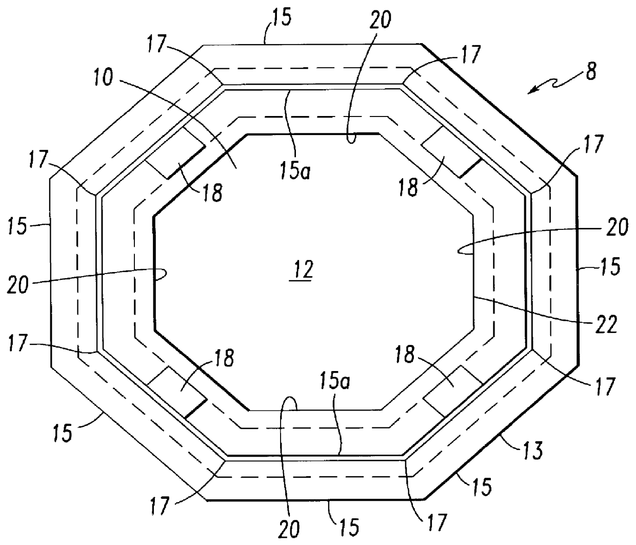
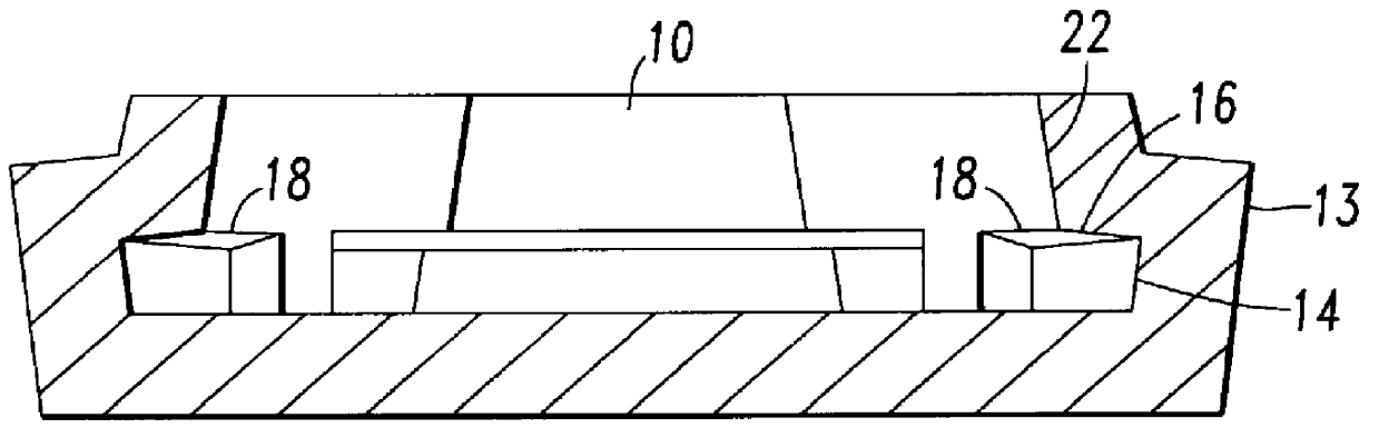
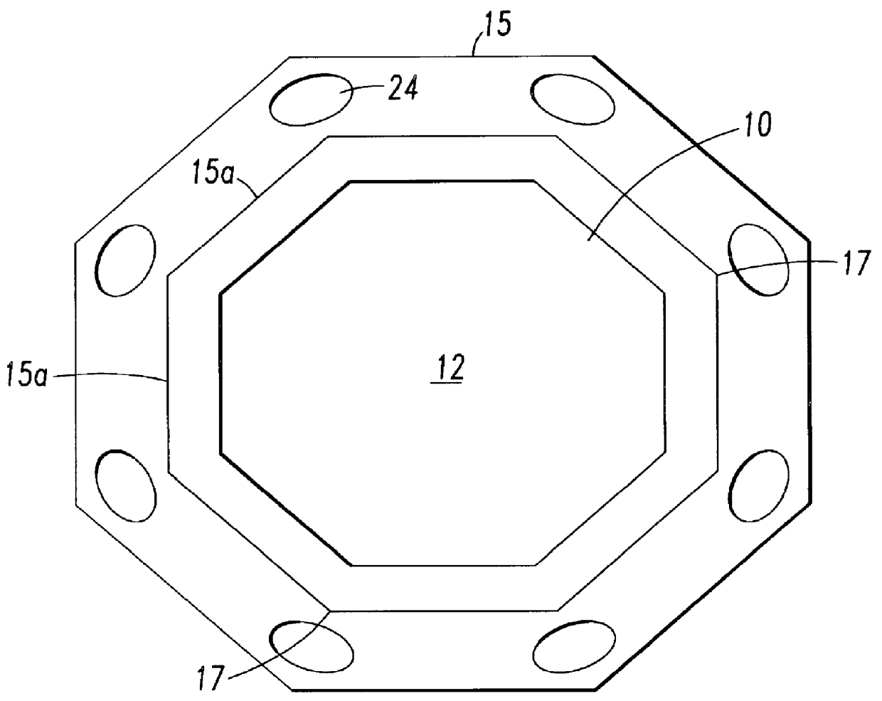
The impact pad of the present invention is a tundish impact pad that receives a stream of liquid metal falling from a ladle into a tundish. The pad radially spreads, then laterally deflects (or reflects) and divides the radial outward flow which is formed by the impact of the downward ladle stream on the base of the pad. The radial outward flow is deflected and divided into multiple discrete, stable and consistent flow patterns or segments. Subsequently, the flow is redirected upwardly and outwardly out of the chamber to the remainder of the tundish volume in a manner which promotes a more homogeneous temperature distribution, promotes an upwardly flow for the flotation of inclusions and entrained slag, and eliminates splash when the tundish level is below the height of the chamber.

Referring now to the drawings wherein like numerals indicate like elements, there is shown in FIG. 1 an impact pad 8 of the present invention. The impact pad 8 is different and unique in its design. As a ...


PUM

PropertyMeasurementUnit
angleaaaaaaaaaa
angleaaaaaaaaaa
angleaaaaaaaaaa

Abstract

A chamber for receiving a downward flow of liquid metal includes a generally horizontal base having a generally planar impact surface. A first faceted sidewall having a plurality of facets formed therein, generally extends upwardly from and encompasses the planar surface to define an interior space. The interior space has an upper opening for receiving the downward flow of liquid metal. A second wall extends inwardly and upwardly from the first faceted wall toward the upper opening. A plurality of buttresses are spaced along the first faceted wall. Each of the buttresses extends between the impact surface and the second faceted wall. The buttresses form a plurality of discrete pockets including at least one facet. The pockets are defined by the buttresses, the impact surface, the first faceted wall and the second wall. The buttresses laterally deflect and divide the radial outward flow into a plurality of discrete flow patterns associated with the plurality of pockets.

Description

1. Field of the InventionThe present invention relates to a tundish impact pad and more particularly to a tundish impact pad that stabilizes the flow of liquid metal exiting the pad.2. Description of the Related ArtLiquid metal, and in particular liquid steel, is often poured from one vessel to another vessel. For example, liquid metal may be poured from a furnace into a ladle, and or from a ladle into a tundish, and or from a tundish into a mold. When liquid metal is poured into the tundish from the ladle, it is normally poured into the tundish through an outlet in the ladle bottom. The stream from the ladle is metered by a valve and the outlet stream may be enclosed in a ceramic tube, called a ladle shroud, which is connected to the valve.A typical tundish has a simple design consisting of either a trough or box shaped vessel having a generally horizontal or flat bottom with vertically arranged walls. In these designs, the stream pouring from the ladle, i.e. incoming ladle stream ...

Claims


Application Information

Patent Timeline
Patent Type & Authority Patents(United States)
IPC IPC(8): B22D41/00
CPCB22D41/003
Inventor HEASLIP, LAWRENCE J.DORRICOTT, JAMES D.
Owner PSC TECH
Why Eureka
Try Eureka