Image generating apparatus and method

a technology which is applied in the field of image generating apparatus and method, can solve the problems of unnatural picture generation, large amount of time required to generate the desired image, and objects in front of it appearing

Inactive Publication Date: 2000-12-05
NIPPON TELEGRAPH & TELEPHONE CORP
View PDF16 Cites 45 Cited by
  • Summary
  • Abstract
  • Description
  • Claims
  • Application Information

AI Technical Summary

Problems solved by technology

In the first method mentioned above, because a defocused picture is generated by removing all hidden surfaces, no matter how much this kind of object in front of the focussed distance is defocused, it is fundamentally impossible to make the objects in front of it appear transparent, and as a result, there is the problem that an unnatural picture is generated.
Additionally, in the second method mentioned above, while this kind of problem basically does not occur, its basis is distributed ray tracing which by nature is very time consuming, and it is necessa

Method used


Image

  • Image generating apparatus and method
  • Image generating apparatus and method
  • Image generating apparatus and method

Examples


first embodiment

[First Embodiment]

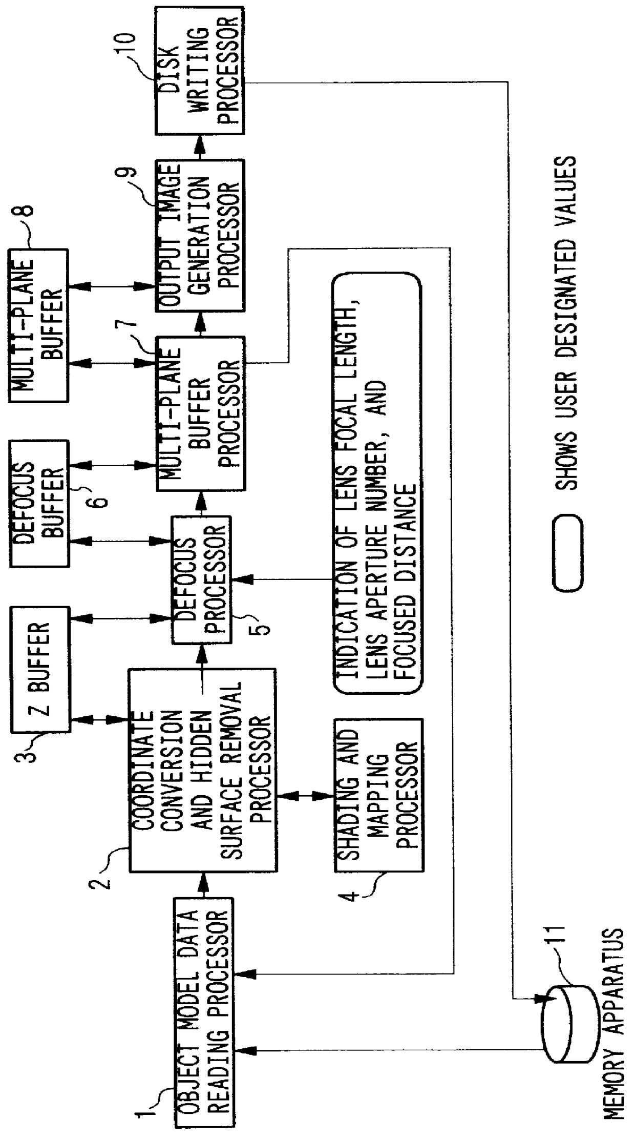
The image generating apparatus of the first embodiment comprises an object model data reading processor 1, a coordinate conversion and hidden surface removal processor 2, a Z buffer 3, a shading and mapping processor 4, a defocus processor 5, a defocus buffer 6, a multi-plane buffer processor 7, a multi-plane buffer 8, an output image generation processor 9, a disk writing processor 10, and a memory apparatus 11.

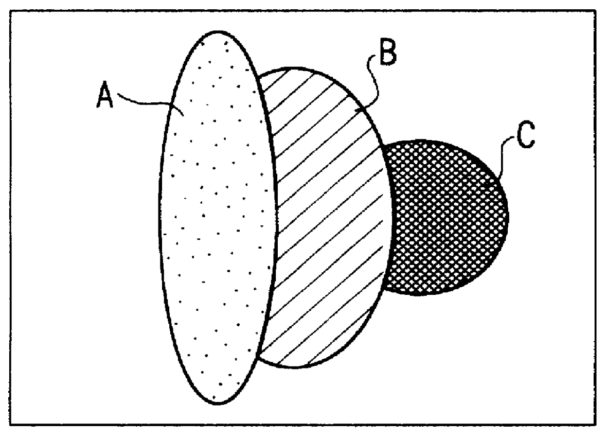
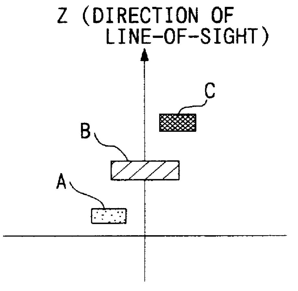
The object model data reading processor 1 reads from the memory apparatus 11 the object model data for each object whose positional relationships are to be represented using the depth of field, and sends the data next to the coordinate conversion and hidden surface removal processor 2. The concept of an object is illustrated in FIGS. 2A and 2B. An object is usually represented by an arrangement (object model data) of a plurality of polygons and basic forms (called "primitives" below). As shown in FIGS. 2A and 2B, the three objects A, B, and C exist, and whe...

second embodiment

[Second Embodiment]

FIG. 12 is a structural diagram of the image generating apparatus of the second embodiment of the present invention.

The present embodiment is composed by adding a background image reading processor 12, a RGBZ conversion processor 13, a switch 14, and a background image buffer 15 to the first embodiment (FIG. 1). Here, the RGBZ conversion processor 13 carries out processing incorporating the Z values into the R, G, and B information.

The background image reading processor 12 reads the background image from the memory apparatus 11, and if the image file format stored in the memory apparatus 11 is not RGB format, first the image format is converted to RGB format. The explanation of the method of conversion is omitted here because it is the same as generally known methods. If the size of the background image is the same as the size x.sub.max and y.sub.max of the image being generated, it is sent as is to the RGBZ conversion processor 13, and if not, processing is carri...

third embodiment

[Third Embodiment]

FIG. 14 is a structural diagram of the image generating apparatus of the third embodiment of the present invention.

The present embodiment is structured by adding to the second embodiment (FIG. 12) a foreground image reading processor 16, a matte area extraction processor 17, and an RGBZ conversion processor 18.

The third embodiment can be executed before the object model data reading processing of the first object as in the second embodiment, or can carry out processing of the next object after finishing the multi-plane buffer processing of a certain object at an arbitrary timing between the beginning and end of the object model data reading, or can execute before the output image generation processing following the end of the multi-plane buffer processing of the last object.

The foreground image reading processor 16 reads from the memory apparatus 11 the image (below called "foreground image") photographed using a blue screen, etc. If the image file format stored in...


PUM


Abstract

An image generating apparatus comprising a multi-plane buffer comprising a plurality of planes, and can record R, G, B, A and Z values as pixels, and a multi-plane buffer processor which stores in said multi-plane buffer in sequence from closest distance from a vantage point a plurality of defocus data which is data consisting of object model data that has been at least coordinate converted, hidden surface processed, and defocus processed, and which assigns R, G, B, A and Z values to each pixel, this object model data being derived from an object whose positional relationships are to be represented from a vantage point using depth of field, which is the effective focus range within which the object is focused.

Description

1. Field of the InventionThe present invention relates to an image generating apparatus and method, in particular an image generating apparatus and method that can quickly generate an image having a natural depth of field and can control the depth of field.This application is based on patent number Hei 9-144024 and Hei 9-217725 filed in Japan, the contents of which are incorporated herein by reference.2. Description of Related ArtConventionally, there are two methods for achieving a realistic depth of field when generating an image by computer graphics: (1) applying a defocus filter to defocus a picture whose entire area focused when generated by conventional methods, (see Potmesil, Michael, et al. "A Lens and Aperture Camera Model for Synthetic Image Generation", Computer Graphics, vol. 17, pp. 137-145, 1981.), and (2) applying distributed ray tracing (see Cook, R. L. et al. "Distributed Ray Tracing", Computer Graphics, vol. 118, pp. 137-145, 1984). One of the most important charac...

Claims


Application Information

Patent Timeline
IPC IPC(8): G06T15/10G06T5/20G06T15/40G06T15/50
CPCG06T5/20G06T15/50G06T15/405
Inventor KOTANI, NAOYA
Owner NIPPON TELEGRAPH & TELEPHONE CORP
Why Eureka
Try Eureka