Sheet feeder for feeding sheets of different rigidity

Inactive Publication Date: 2000-12-12
BROTHER KOGYO KK
View PDF3 Cites 41 Cited by
  • Summary
  • Abstract
  • Description
  • Claims
  • Application Information

AI Technical Summary

Problems solved by technology

However, if thick post cards, envelopes or other relatively rigid sheets are stacked in the cassette, their front ends may be stopped by the rear end face of the holder, and may not transfer or move smoothly onto the upper surface

Method used


Image

  • Sheet feeder for feeding sheets of different rigidity
  • Sheet feeder for feeding sheets of different rigidity
  • Sheet feeder for feeding sheets of different rigidity

Examples


Example

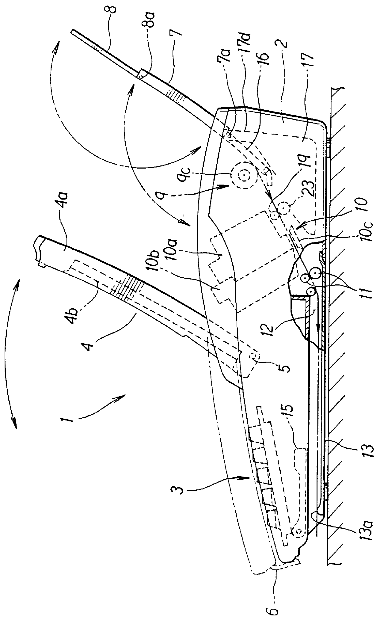
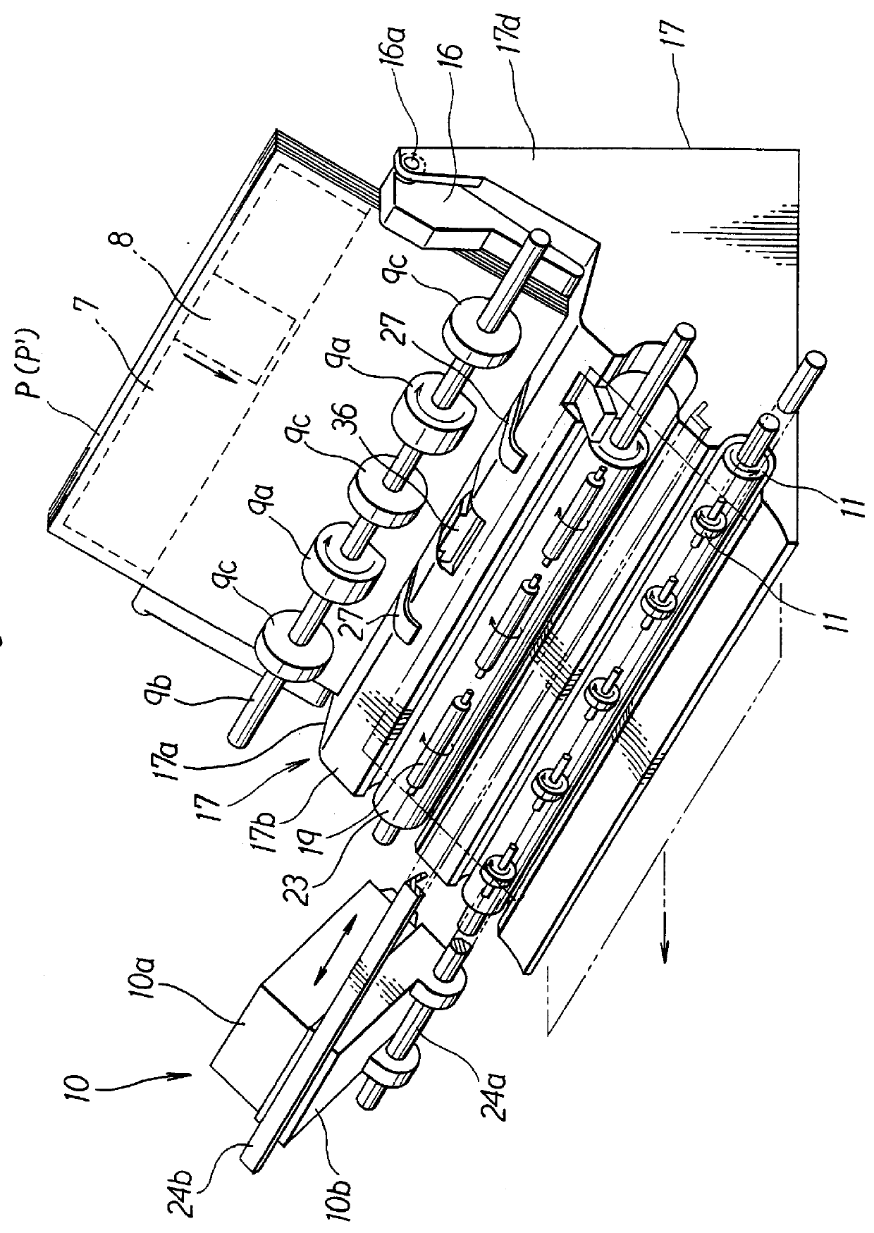
With reference to FIGS. 1-3, a portable word processor 1 embodying the invention includes a housing 2, which may be made of synthetic resin. Various keys are arranged in a key entry area 3, which is formed at the top of a front portion of the housing 2.

A display unit 4 includes a liquid crystal display 4b. The back of the display 4b is covered with a cover 4a, which may be made of synthetic resin. The display unit 4 is supported at its one end pivotably through a horizontal shaft 5 by the housing 2 in the rear of the entry area 3. While the word processor 1 is used, the display unit 4 can be kept open in a backwardly inclined position as shown with solid lines in FIG. 1. While the processor 1 is not used or is carried, the display unit 4 can be closed with its display 4b positioned over the entry area 3 and protected by the cover 4a, as shown with two-dot chain lines in FIG. 1. The free end of the display unit 4 can be fastened through a hook 6 to the front end of the housing 2.

Posi...


PUM


Abstract

A sheet feeder includes a support plate inclined backward and a feed roller for feeding one by one the sheets of paper stacked on the plate. A first support surface and a second support surface are formed at or near the bottom of the plate to support the front ends of the sheets. The second surface is lower in frictional resistance than the first surface. The second surface can be moved by an operating lever between a first position, where it is protruded from the first surface toward the sheets, and a second position, where it is retracted from the first surface away from the sheets. If the sheets are relatively rigid, their front ends are supported by the second surface in the first position, and they can therefore be fed smoothly.

Description

1. Field of the InventionThe present invention relates to a cut sheet feeder for a word processor, an electrophotographic copier, a printer, a facsimile machine or another image forming apparatus.2. Description of Related ArtFor example, the assignee's Japanese Patent Application Laid-Open No. 7-304527 discloses a conventional printer, which includes an operation panel formed in a front portion of the top of its housing. A sheet cassette is positioned in the rear of the panel, and held removably in an backwardly inclined position by the housing. A cut sheet of paper can be fed from the cassette toward a print unit (image forming unit), which is supported in the housing.The sheet cassette includes a support plate, which is urged upward. The cassette also includes a bottom support in the form of a bank. The front or lower ends of the sheets stacked on the support plate are stopped by the bottom support. Semi-cylindrical pickup rollers are supported downstream from the bottom support, ...

Claims


Application Information

Patent Timeline
IPC IPC(8): B65H3/06B65H3/52B41J13/00
CPCB65H3/0661B65H2404/1112B65H2405/1136B65H2405/113B65H2404/531B65H3/56B65H7/00B65H2511/212B65H2515/81B65H2511/16B65H2220/01B65H2220/11B65H2220/04
Inventor MURAKI, MOTOHITO
Owner BROTHER KOGYO KK
Why Eureka
Try Eureka