Method and apparatus for an improved single pole double throw micro-electrical mechanical switch

a micro-electromechanical switch and switch technology, applied in the direction of electrostrictive/piezoelectric relays, electric apparatus, relays, etc., can solve the problems of the opening and closing ("transition speed") of the conventional mem switch and the failure of the switch to clos

Inactive Publication Date: 2000-12-12
RAYTHEON CO
View PDF6 Cites 196 Cited by
  • Summary
  • Abstract
  • Description
  • Claims
  • Application Information

AI Technical Summary

Problems solved by technology

Unfortunately, electrostatically actuated MEM switches constructed in accordance with conventional teachings typically close faster than they open and often suffer "stiction" e

Method used


Image

  • Method and apparatus for an improved single pole double throw micro-electrical mechanical switch
  • Method and apparatus for an improved single pole double throw micro-electrical mechanical switch
  • Method and apparatus for an improved single pole double throw micro-electrical mechanical switch

Examples


Embodiment Construction

Illustrative embodiments and exemplary applications will now be described with reference to the accompanying drawings to disclose the advantageous teachings of the present invention.

While the present invention is described herein with reference to illustrative embodiments for particular applications, it should be understood that the invention is not limited thereto. Those having ordinary skill in the art and access to the teachings provided herein will recognize additional modifications, applications, and embodiments within the scope thereof and additional fields in which the present invention would be of significant utility.

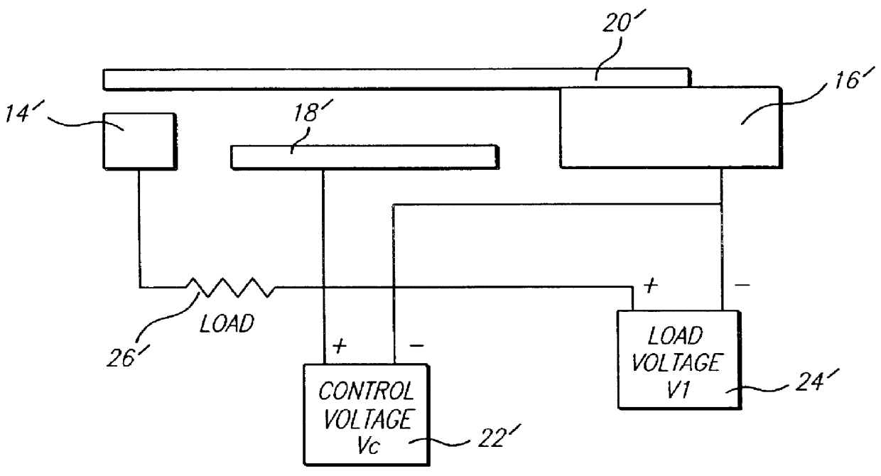
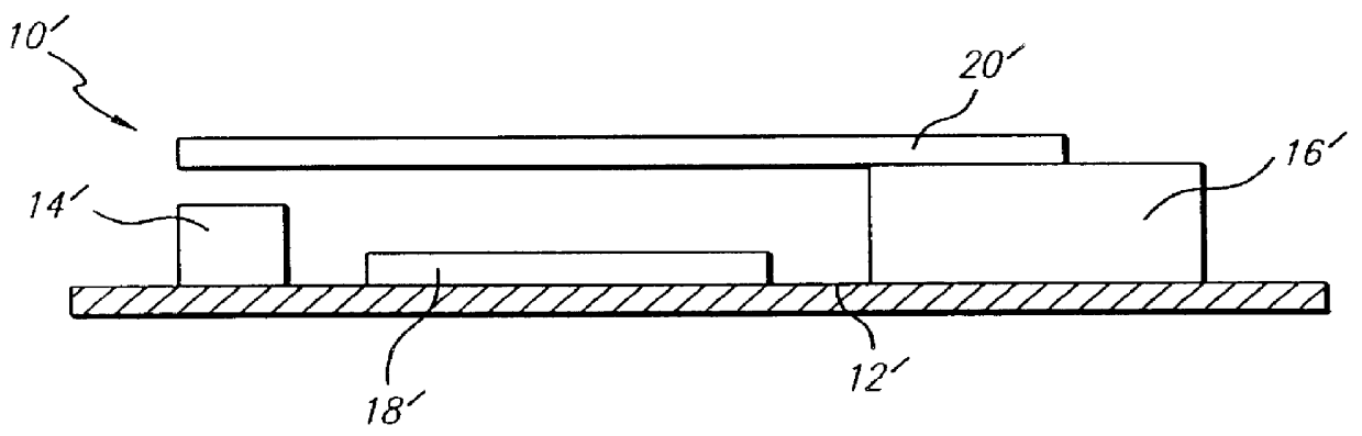
FIG. 1 is a diagram of a conventional micro-electromechanical (MEM) switch. The switch 10' has an insulating support substrate 12' which serves as a base. A conductive contact 14' is mounted on one side of the substrate and a cantilever support 16' is mounted on the other. The cantilever support 16' supports a conductive cantilever beam 20'. A conductive control...


PUM


Abstract

A single pole, double throw micro-electromechanical (MEM) switch. The inventive switch includes a first contact providing a first terminal of the switch. A second contact provides a second terminal of said switch. A cantilever beam provides a third terminal of the switch. The inventive switch includes a system for electrostatically pushing or pulling the beam to disengage the first contact and engage the second contact. In an illustrative implementation, the system for electrostatically operating the switch includes a first charge storage structure on the beam, a second charge storage structure on the switch, and an electrical supply for creating an electrical charge on the first and the second charge storage structures. The first and second charge storage structures are effective to create a force of repulsion therebetween on the application of an electrical charge thereto. The "pull" electrostatic force closes the MEM switch. The "push" force aids in opening the switch. The "push" capability is the result of the use of like (same polarity) electrostatic charges on the control surfaces. The like charges provide an electrostatic repulsion force during the switch opening process.

Description

1. Field of the InventionThe present invention relates to electrical and electronic circuits and components. More specifically, the present invention relates to micro-electromechanical (MEM) switches.2. Description of the Related ArtAn electrostatic MEM switch is a switch operated by an electrostatic charge and manufactured using micro-electromechanical techniques. A MEM switch may control electrical, mechanical, or optical signal flow. Current MEM switches are usually single pole, single throw (SPST) configurations having a rest state that is normally open. Application of an electrostatic charge to the control electrode (or opposite polarity electrostatic charges to a two-electrode design) will create an attractive electrostatic force ("pull") on the switch causing the switch to close. Currently, the switch opens by removal of the electrostatic charge on the control electrode(s), allowing the mechanical spring restoration force of the armature to open the switch.Unfortunately, elec...

Claims


Application Information

Patent Timeline
IPC IPC(8): H01H59/00
CPCH01G5/18H01H59/0009
Inventor MCMILLAN, LEE A.STREETER, ROBERT D.
Owner RAYTHEON CO
Why Eureka
Try Eureka