Method of reducing wind gust loads acting on an aircraft

a technology of wind gusts and aircraft, applied in the direction of process and machine control, instruments, energy saving arrangements, etc., can solve the problems of inability to use systems, slow or gradual variation of maneuver load, and low efficiency of aircraft, so as to reduce the total resulting load, and reduce the total wing load

Inactive Publication Date: 2000-12-19
DAIMLER CHRYSLER AEROSPACE AIRBUS
View PDF14 Cites 103 Cited by
  • Summary
  • Abstract
  • Description
  • Claims
  • Application Information

AI Technical Summary

Benefits of technology

Moreover, the present invention takes a totally different approach as compared to the prior art for reducing the total wing loading and particularly wing bending loading that arises when a wind gust acts on the wing. As discussed above, the total load at the time of a wind gust includes a first component represented by the 1 g basis load, plus a second component represented by the additional load induced by the wind gust itself. The prior art systems and methods aim to actively sense and counteract the second component of this equation, i.e. the variable additional load induced by the wind gust itself. In contrast, the present inventive method essentially ignores the active variations

Problems solved by technology

Such sudden variations in the angle of attack correspondingly cause sudden variations in the instantaneous lift, and consequently cause sudden variations in the gust induced loading of the aircraft and particularly the wings.
On the other hand, maneuver load variations are relatively slow or gradual, because they are induced by relatively slow control surface deflections or flight attitude and configuration changes, for example resulting in a maneuvering load transitioning from 1 g to 2.5 g.
On the other hand, while the prior art has proposed systems for reducing wind gust loads, such systems have not come into practical use.
Namely, since the w

Method used


Image

  • Method of reducing wind gust loads acting on an aircraft

Examples


Embodiment Construction

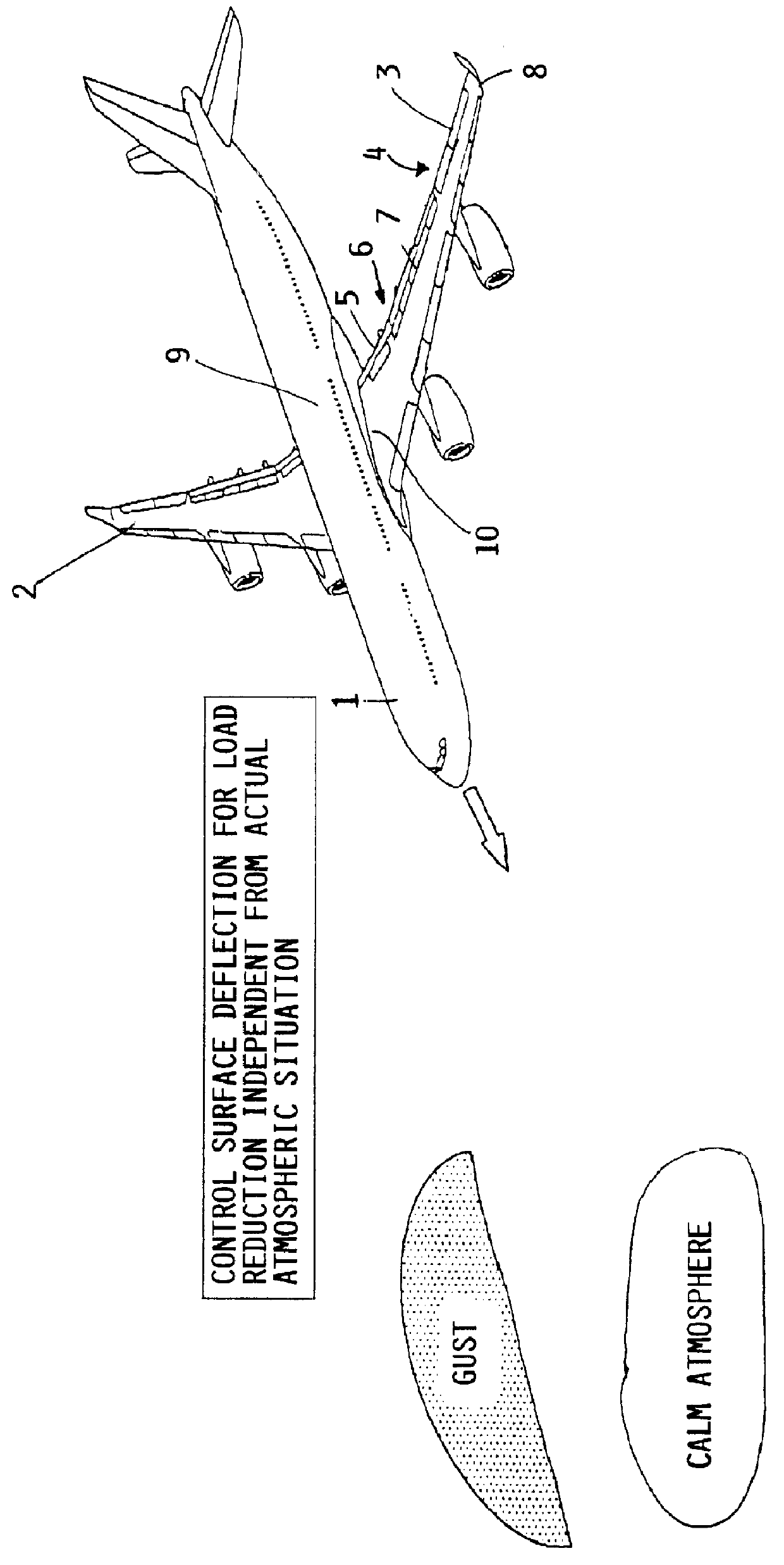
As shown in the single drawing FIGURE, the inventive reconfiguration or redistribution of the lift generation along the wing 2 of an aircraft 1 span of the wings can be achieved by correspondingly actuating and deflecting control surfaces such as the ailerons 3 provided at the outer portions 4 of the wings 2 and the flaps 5 provided at the inner portions 6 of the wings 2. Spoilers 7 at either of these locations can also be used. As a further variation, the inventive method can be used in connection with adaptive wings or wings having a variable camber or a twistably variable angle of attack, by actively or passively varying or adapting the configuration of such wings to achieve the required distribution of the lift characteristic.

Throughout this specification, the terms "outer portion" and "inner portion" of the wing are merely relative, and can refer to an outer half and an inner half of a wing, or an outer third and an inner third of a wing, or an outer two thirds and an inner one...


PUM


Abstract

A method of reducing the bending moment effect of wind gust loads acting on the wing of an aircraft involves adjusting the aerodynamic configuration of the wing so as to alter the distribution of lift generated by the wing during phases of flight in which critical wind gusts are expected to occur. Particularly, during climb and descent phases of flight below cruise altitude, the lift generated by outboard portions of the wings is reduced while the lift generated by inboard portions of the wings is increased. Thereby, the 1 g basis load acting on the outboard portions of the wings is reduced, and consequently the total load applied to the outboard portions of the wings, resulting from the 1 g basis load plus the additional wind gust load, is correspondingly reduced. This leads to a reduction of the bending moments effective on the wings, and of any rolling moment effective on the aircraft. The required adjustment of the lift distribution is preferably achieved by deflecting the ailerons of both wings symmetrically upward and/or deflecting the flaps of both wings symmetrically downward during climb and descent. The adjustment of the wing configuration is carried out dependent only on flight parameters such as the altitude, speed and gross weight, and does not require rapid sensing of the occurrence of a wind gust and rapid actuation of control surfaces to try to instantaneously counteract a wind gust as it occurs.

Description

PRIORITY CLAIMThis application is based on and claims the priority under 35 U.S.C. .sctn.119 of German Patent Application 198 19 341.6, filed on Apr. 30, 1998, the entire disclosure of which is incorporated herein by reference.1. Field of the InventionThe invention relates to a method for reducing wind gust loads acting on an aircraft by selectively positioning control surfaces of the wings of the aircraft in order to reduce the total load acting on the wings, which includes a gust load component.2. Background InformationThe total load acting on an aircraft, and particularly the total load resulting in a bending moment applied to an aircraft wing, is given by the sum of the 1 g basis load, the additional load arising from the influence of wind gusts, and the additional load resulting from maneuvers being carried out by the aircraft. The total 1 g basis load is represented by the lift forces generated by the aircraft in order to lift the weight of the aircraft, and is substantially c...

Claims


Application Information

Patent Timeline
IPC IPC(8): B64C13/00B64C13/16G05D1/00G05D1/04B64C9/12G05D1/02
CPCB64C13/16G05D1/046G05D1/0005Y02T50/44G05D1/0066Y02T50/40
Inventor KELM, ROLANDGRABIETZ, MICHAEL
Owner DAIMLER CHRYSLER AEROSPACE AIRBUS
Why Eureka
Try Eureka