
Apparatus for manufacturing composite parts produced by resin transfer molding

a technology of resin transfer molding and composite parts, which is applied in the direction of auxillary shaping apparatus, manufacturing tools, cocoa, etc., can solve the problems of preventing the penetration of resin into the preform, and reducing the production efficiency of the preform

Inactive Publication Date: 2001-01-02
SOC NATIONALE INDUSTRIELLE AEROSPATIALE SA
View PDF9 Cites 33 Cited by
  • Summary
  • Abstract
  • Description
  • Claims
  • Application Information

AI Technical Summary

Benefits of technology

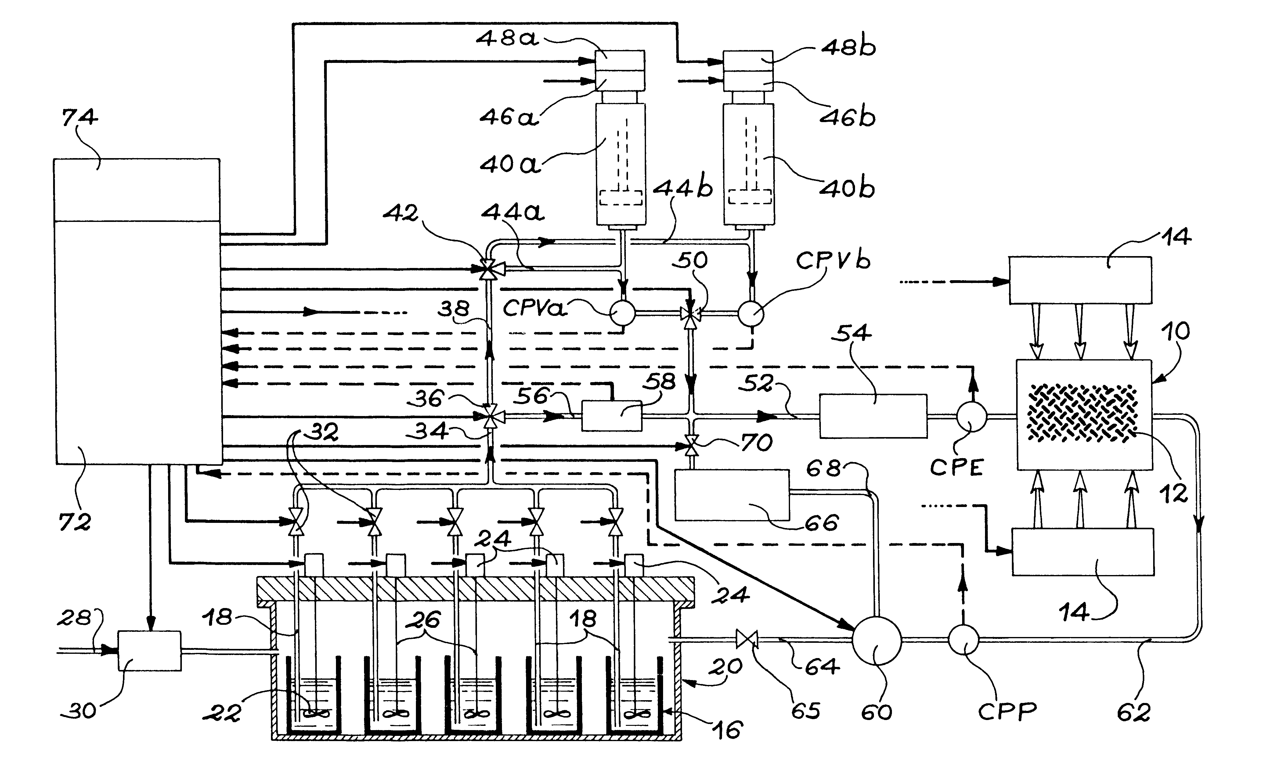
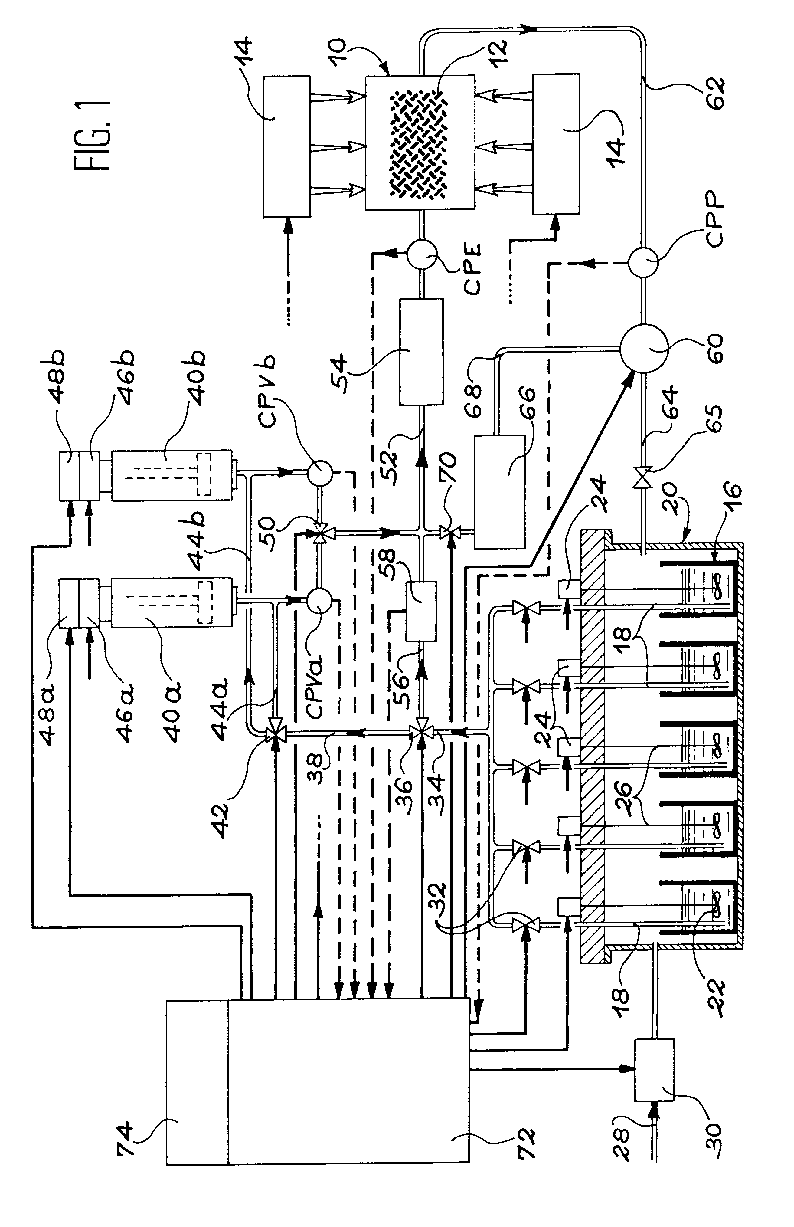
In the preferred embodiment of the invention two injection cylinders are mounted in parallel between a second three-way valve comprising a inlet connected to the resin supply vessel and a third three-way valve comprising an outlet connected to the mold. In controlled flow-rate mode, the control means actuate these second and third three-way valves so that one of the injection cylinders is connected to the resin supply vessel and isolated from the mold while the other injection cylinder is connected to the mold and isolated from the resin supply vessel, and conversely. This arrangement makes it possible to inject resin continuously into the mold from each injection cylinder alternately. It is therefore particularly well suited to the manufacture of large-sized parts and contributes to reducing the risks of the resin starting to polymerize in the cylinders.

Problems solved by technology

However, the RTM procedures in the known art do not allow for the manufacture of large-sized parts with this degree of compression.
The considerable loss of pressure introduced by the compressed textile fibers in the preform inhibits the penetration of resin into the preform.
The highly compressed textile fibers also constitute an obstacle to the penetration of the resin and may leave entire areas of a part unimpregnated as well as leaving bubbles.
For these various reasons the RTM technique is currently little used for the manufacture of large parts with a high fiber content.
This characteristic of the existing apparatuses also tends to make them very unsuitable for the aerospace industry in which parts with widely differing characteristics are produced in limited series.
However, the specific drawbacks of the RTM technique described above have hitherto prevented the techniques used for RTM injection molded production being adapted to produce large parts with high or low fiber contents as required.

Method used


Image

  • Apparatus for manufacturing composite parts produced by resin transfer molding
  • Apparatus for manufacturing composite parts produced by resin transfer molding
  • Apparatus for manufacturing composite parts produced by resin transfer molding

Examples


Embodiment Construction

In the preferred embodiment shown schematically in FIG. 1, the apparatus according to the invention comprises one or more molds 10 suitable for manufacturing composite parts using resin transfer molding. The cavity (not shown) of each mold 10 is constructed so that its shape and measurements correspond to the external characteristics of the part to be produced. The cavity is designed to accept a fibrous preform 12 made of preassembled dry organic fibers. Each mold 10 is fitted with heating means (not shown) designed to maintain the mold at the required temperature during injection of the resin and to subject it to a polymerization cycle when the injection phase has been completed.

Each mold 10 is also fitted with compression means indicated by arrows 14 in FIG. 1. These compression means 14 are designed to apply a controlled compression force with an adjustable value to fibrous preform 12. As a non-limitative example, said compression means 14 may comprise one or more inflatable blad...


PUM

PropertyMeasurementUnit
porosityaaaaaaaaaa
pressureaaaaaaaaaa
constant pressureaaaaaaaaaa

Abstract

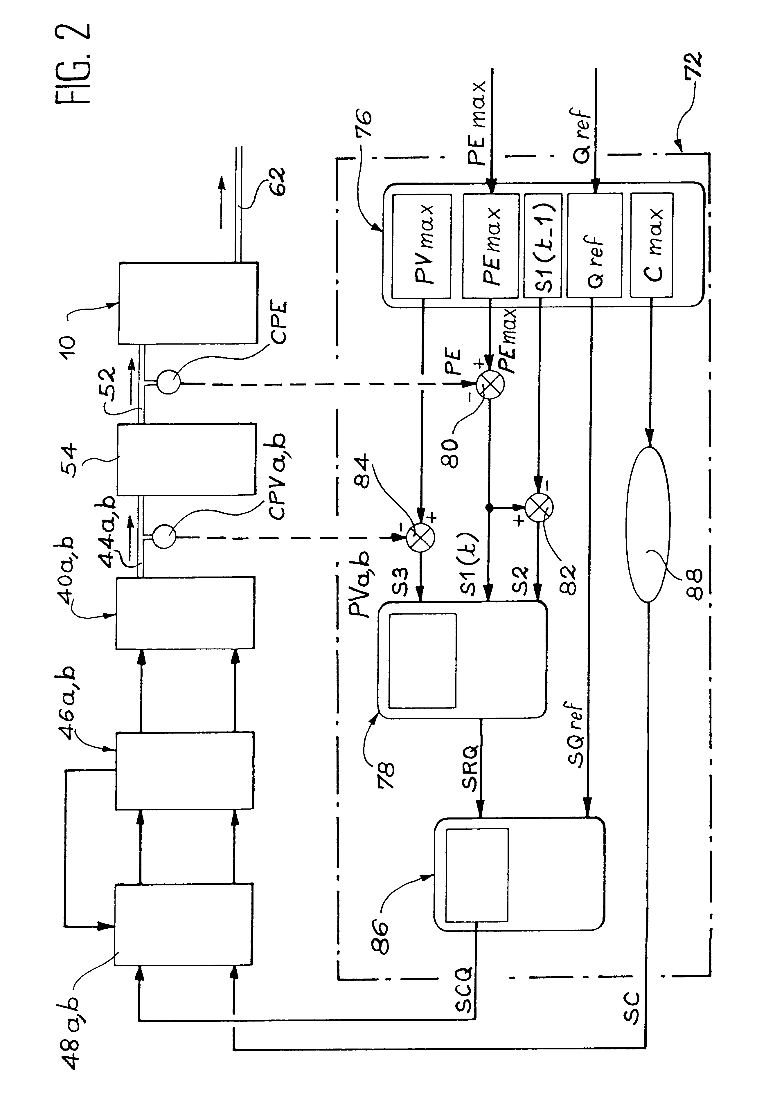
An apparatus for manufacturing composite parts produced by resin transfer molding (RTM) is configured to operate in controlled flow-rate mode or controlled pressure mode to use the RTM technique for manufacturing large-sized composite parts with a low fiber content. In both modes, control is by means of a fuzzy logic control card. In controlled flow-rate mode the resin is injected alternately by two injection cylinders (40a and 40b) controlled by motors whose speed is controlled. In controlled pressure mode the resin is injected directly from resin supply vessels (16) subjected to pressure controlled by an air regulator (30).

Description

DESCRIPTION1. Field of the InventionThe present invention relates to an apparatus for manufacturing composite parts produced by resin transfer molding (RTM).More precisely, the apparatus according to the invention is designed for producing large-size composite parts that may either have a high fiber content, i.e. 58% or greater, or a lower fiber content, i.e. below 54%.This type of apparatus is particularly used for applications in the aerospace industry in which large-size parts with a high fiber content are used in conjunction with large-size sandwich parts in which the fiber content of the skins covering the core of the sandwich structure is relatively low.2. Background ArtThe RTM technique has been used for many years in fields such as the automobile and producer's goods industries to produce parts with a relatively low fiber content, i.e. lower than 54%. It consists of inserting a dry fibrous preform into a mold and then using low pressure to inject a liquid organic resin into ...

Claims


Application Information

Patent Timeline
Patent Type & Authority Patents(United States)
IPC IPC(8): B29C45/77B29C70/04B29C70/54B29C70/48
CPCB29C70/48B29C70/546B29C70/40B29C2037/90
Inventor BOIME, BERNARDFILLEUL, DIDIER
Owner SOC NATIONALE INDUSTRIELLE AEROSPATIALE SA
Learn More