Internal combustion engine with a single crankshaft and having opposed cylinders with opposed pistons

a technology of opposed pistons and internal combustion engines, which is applied in the direction of combustion engines, reciprocating piston engines, positive displacement engines, etc., can solve the problems of limiting the designers' options on how the engine is placed within the vehicle, reducing the efficiency of raw emissions, and reducing the efficiency of internal combustion engines

Inactive Publication Date: 2001-01-09
ADVANCED PROPULSION TECH +1
View PDF30 Cites 308 Cited by
  • Summary
  • Abstract
  • Description
  • Claims
  • Application Information

AI Technical Summary

Benefits of technology

An important feature of the invention is that the geometrical configurations and masses of the moving parts are selected so as to minimize the dynamic imbalance of the engine during its operation. More specifically, it is preferred to choose the effective mass of each outer piston such that the product of that mass times the throw of the associated crankshaft journal will be essentially equal to the product of the effective mass of each inner piston times the throw of its associated crankshaft journal. This configuration substantially eliminates dynamic imbalance.
According to a further preferred feature of the invention, the pullrod and pushrod journals for each cylinder are arranged asymmetrically so that the exhaust ports of the associated cylinder open before its air intake ports open, and close before its air intake ports close. This asymmetric timing makes it possible to utilize superchargers to enhance engine efficiency.
To provide the asymmetric intake and exhaust port timing of the invention while substantially preserving the dynamic balance, one of the cylinders has the air intake ports on its inner end adjacent the crankshaft, while the other cylinder has its air intake ports on its outer end remote from the crankshaft.
Yet another preferred feature of the invention is that each inner piston on its end remote from the combustion chamber has a smooth end face that is convexly curved in a plane perpendicular to the longitudinal axis of the crankshaft. An associated pushrod assembly then includes a connecting rod coupled to one journal on the crankshaft and has a concavely shaped outer end surface that slidingly engages the curved end face of the inner piston. This pushrod configuration serves to effectively lengthen the pushrods, thereby reducing friction losses and improving dynamic balance.

Problems solved by technology

Despite the promise of external continuous combustion technologies such as Stirling engines and fuel cells to eventually provide low-emission high-efficiency engines for automobiles and light aircraft, these technologies will not be viable alternatives to internal combustion engines in the near future due to their inherent disadvantages in weight, space, drivability, energy density and cost.
The need for at least four cylinders to achieve a suitable rate of power stroke production dictates the size and shape of this engine, and therefore also greatly limits the designers' options on how the engine is placed within the vehicle.
The small cylinders of these engines are typically not optimal for efficient combustion or the reduction of raw emissions.
The four cylinder in-line configuration also has drawbacks with respect to passenger comfort, since there are significant unbalanced free-mass forces which result in high noise and vibration levels.
Two-stroke engines, however, have seen limited use because of several perceived drawbacks.
Two-stroke engines have a disadvantage in mean effective pressure (i.e., poorer volumetric efficiency) over four-stroke engines because a significant portion of each stroke must be used for the removal of the combustion products of the preceding power stroke (scavenging) and the replenishment of the combustion air, and is therefore lost from the power stroke.
Scavenging is also inherently problematic, particularly when the engine must operate over a wide range of speeds and load conditions.
Two-stroke compression-ignition (Diesel) engines are known to have other drawbacks as well, including poor starting characteristics and high particulate emissions.
The largest sources of friction loss in current production automotive engines, accounting for approximately half of all friction losses, are the result of the lateral forces produced by the rotating connecting rods acting on the pistons, pushing them against the cylinder walls.
Another significant source of friction loss in current production engines are the large forces acting on the crankshaft main bearings.

Method used


Image

  • Internal combustion engine with a single crankshaft and having opposed cylinders with opposed pistons
  • Internal combustion engine with a single crankshaft and having opposed cylinders with opposed pistons
  • Internal combustion engine with a single crankshaft and having opposed cylinders with opposed pistons

Examples


Embodiment Construction

1. Overview

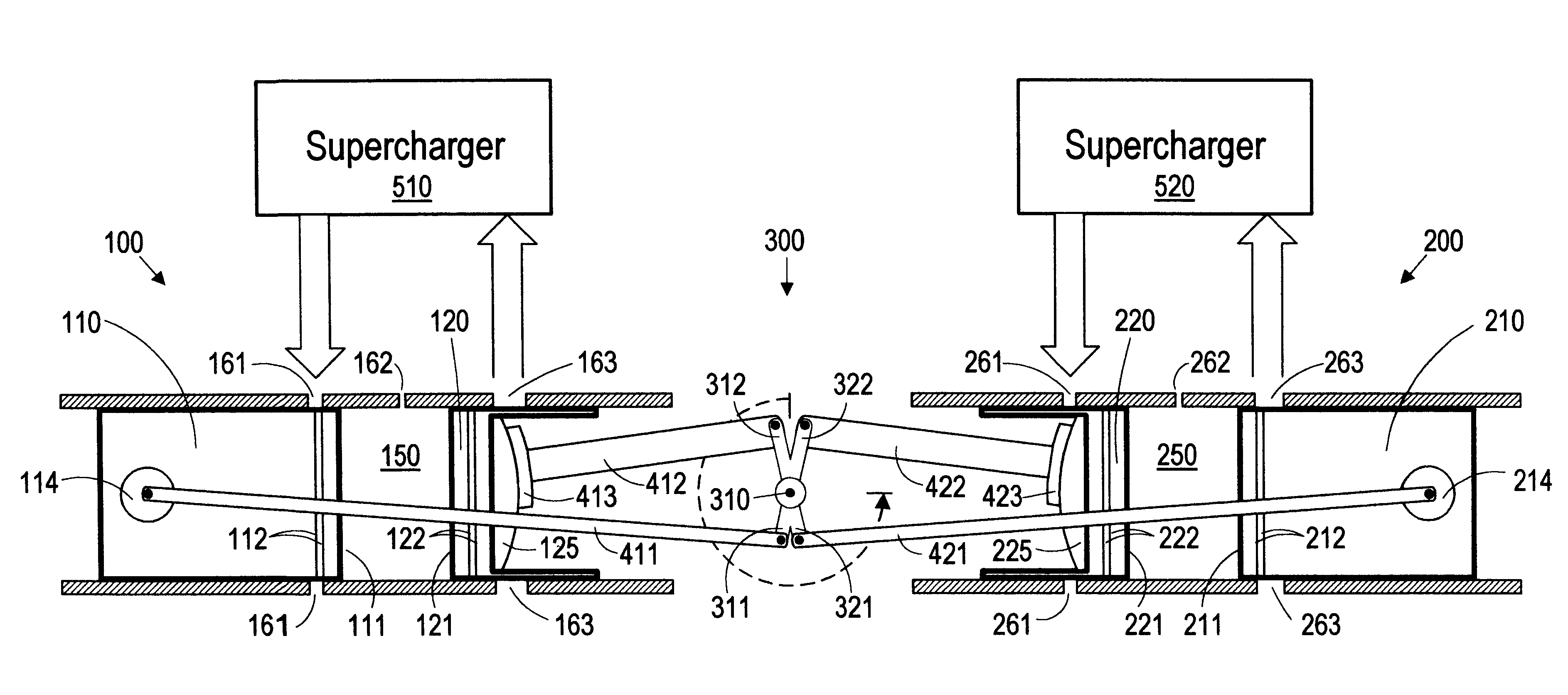
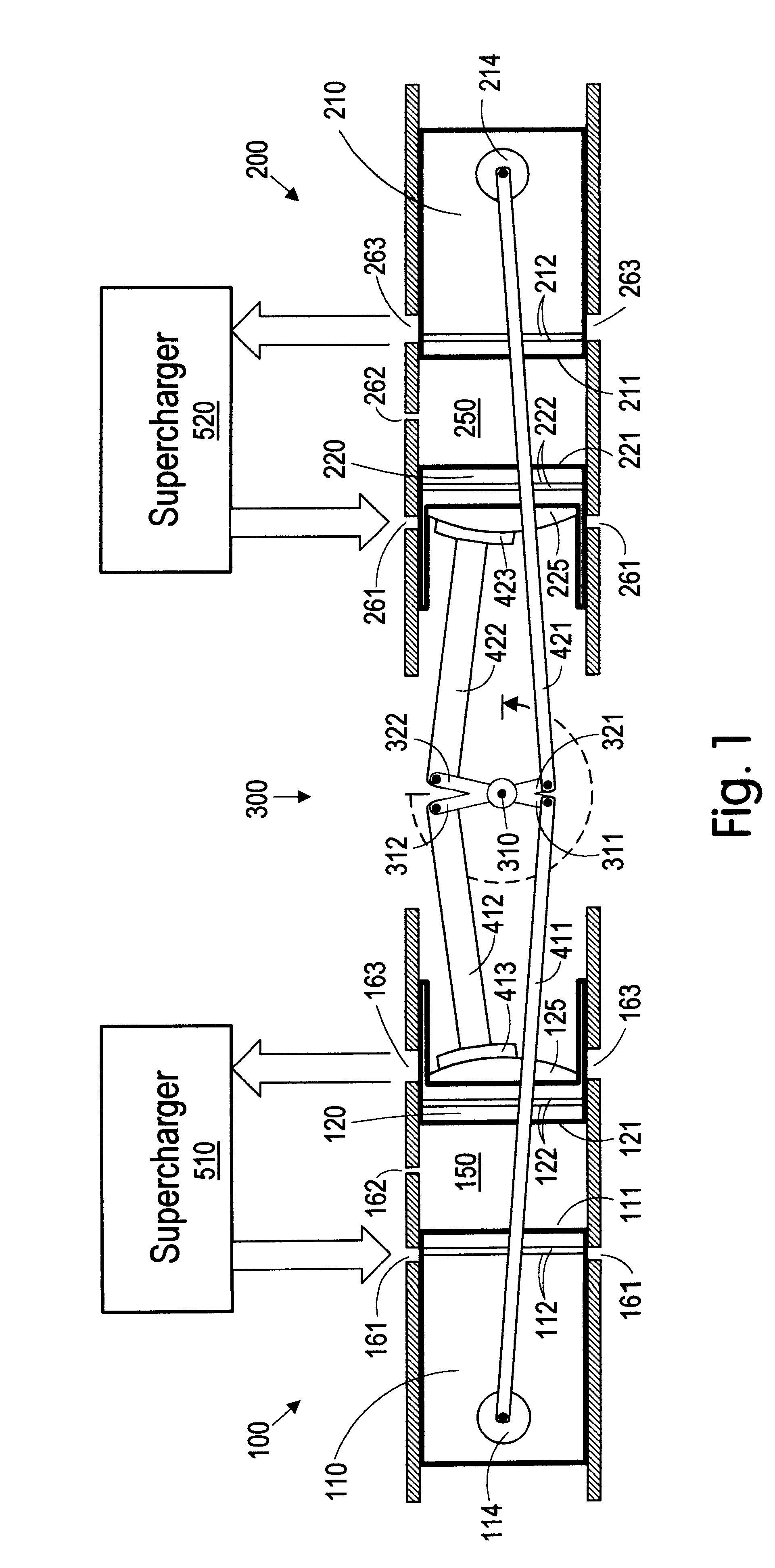
As illustrated in FIG. 1, the engine configuration of the present invention comprises a left cylinder 100, a right cylinder 200, and a single central crankshaft 300 located between the cylinders (for clarity, the supporting structure of the engine is omitted from FIG. 1).

The left cylinder 100 has an outer piston 110 and an inner piston 120, with combustion faces 111 and 121 respectively, the two pistons forming a combustion chamber 150 between them. The right cylinder 200 similarly has an outer piston 210, an inner piston 220, with combustion faces 211 and 221 and combustion chamber 250. Each of the four pistons 110, 120, 210, and 220 are connected to a separate eccentric on the crankshaft 300.

The outer piston 110 of the left cylinder is connected to crankshaft eccentric 311 by means of pullrod 411; the outer piston 210 of the right cylinder is similarly connected to crankshaft eccentric 321 by pullrod 421. While single pullrods are shown in FIG. 1, in the preferred embod...


PUM


Abstract

A two-stroke internal combustion engine is disclosed having opposed cylinders, each cylinder having a pair of opposed pistons, with all the pistons connected to a common central crankshaft. The inboard pistons of each cylinder are connected to the crankshaft with pushrods and the outboard pistons are connected to the crankshaft with pullrods. This configuration results in a compact engine with a very low profile, in which the free mass forces can be essentially totally balanced. The engine configuration also allows for asymmetrical timing of the intake and exhaust ports through independent angular positioning of the eccentrics on the crankshaft, making the engine suitable for supercharging.

Description

The present invention relates generally to two-stroke internal combustion engines, and more specifically to a two-stroke internal combustion engine having two opposed cylinders, each cylinder having a pair of opposed pistons.1. IntroductionThe design and production of internal combustion engines for the automotive and light aircraft industries are well-developed fields of technology. To be commercially viable, any new engine configuration must, without sacrificing performance, provide significant improvements in the areas of energy and raw material conservation (especially the improvement of fuel consumption), environmental protection and pollution control, passenger safety and comfort, and competitive design and production methods that reduce cost and weight. An improvement in one of these areas at the expense of any other is commercially unacceptable.A new engine configuration must be mechanically simple so that mechanical losses are inherently minimized, and must be well-suited t...

Claims


Application Information

Patent Timeline
Patent Type & Authority Patents(United States)
IPC IPC(8): F02B75/24F02B75/00F02B25/00F02B25/08F02B75/02
CPCF02B25/08F02B75/246F02B2075/025
Inventor HOFBAUER, PETER
Owner ADVANCED PROPULSION TECH
Why Eureka
Try Eureka